Optical fiber wiring device

A technology of optical fiber wiring and photoelectric switch, applied in the field of optical fiber wiring devices, can solve the problems of low efficiency of optical fiber wiring, etc., and achieve the effect of improving configuration efficiency

Inactive Publication Date: 2016-09-07
GUILIN TRYIN TECH CO LTD
View PDF5 Cites 3 Cited by
  • Summary
  • Abstract
  • Description
  • Claims
  • Application Information

AI Technical Summary

Problems solved by technology

[0003] The invention provides an optical fiber configuration device to solve the problem of low efficiency of optical fiber wiring

Method used


Image

  • Optical fiber wiring device

Examples


Embodiment Construction

[0016] The present invention will be further described below in conjunction with examples, but the present invention is not limited to these examples.

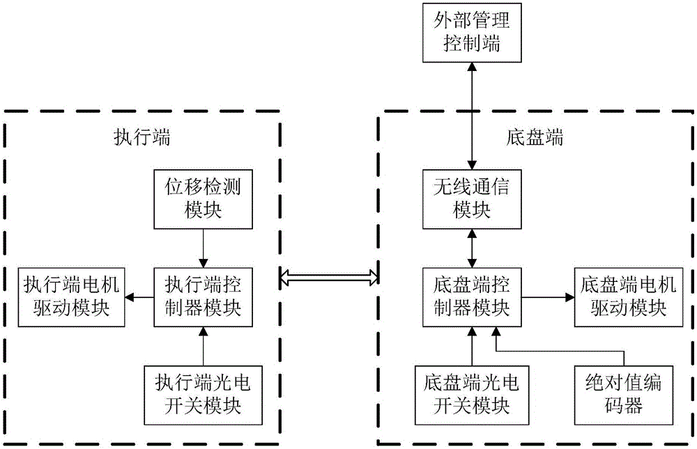
[0017] The optical fiber distribution device includes the execution end and the chassis end, the execution end is connected to the chassis end; the chassis end includes the chassis end controller module, the absolute encoder, the chassis end photoelectric switch module and the chassis end motor drive module; the absolute value encoder The output terminal is connected to the chassis-side controller module; the output terminal of the chassis-side photoelectric switch module is connected to the chassis-side controller module; the input terminal of the chassis-side motor drive module is connected to the controller module; the controller module is connected to the execution terminal; the execution terminal It includes a displacement detection module, a photoelectric switch module at the execution end, a controller module at the exec...


PUM


Abstract

The invention provides an optical fiber wiring device, which is provided with a base plate terminal and an execution terminal, and is characterized in that an initial zero point position of a measuring shaft is acquired at the base plate terminal, a base plate terminal motor driving module drives a motor, a base plate is driven to move to an initial slot position, the execution terminal acquires relative displacement that an execution terminal manipulator needs to run on the basis of data of a displacement detection module and an execution terminal photoelectric switch module according to a wiring instruction sent by the base plate terminal, and the motor drives the manipulator to implement insertion and extraction actions of optical fiber wiring under driving of an execution terminal motor driving module; the base plate terminal drives the base plate to the next slot position after receiving wiring completion information of the execution terminal, and then the execution terminal implements insertion and extraction. The whole process is of full automation configuration, and the optical fiber configuration efficiency is improved; and the optical fiber wiring device is provided with a wireless communication module, and an optical fiber wiring instruction is sent by an external management control terminal so as to realize remote optical fiber configuration.

Description

technical field [0001] The invention relates to the distribution technology, especially the optical fiber distribution device. Background technique [0002] At present, infrequent optical switching is completed by manual optical fiber distribution frames, and the configuration of optical fiber lines is realized through manual insertion and removal of flanges and manual wiring. This mechanical wiring method is very inefficient, but it will still take a long time For a period of time, it is necessary to propose an automatic optical fiber distribution device to improve the efficiency of optical fiber distribution. Contents of the invention [0003] The invention provides an optical fiber configuration device to solve the problem of low efficiency of optical fiber distribution. [0004] The present invention solves the above problems through the following technical solutions: [0005] The optical fiber distribution device includes an execution end and a chassis end, and the ...

Claims


Application Information

Patent Timeline
Patent Type & Authority Applications(China)
IPC IPC(8): G02B6/44
CPCG02B6/4439
Inventor 姚峰
Owner GUILIN TRYIN TECH CO LTD
Why Eureka
Try Eureka