Pressure relief controlling regulating valve with pressure capable of being visible

A technology for controlling and regulating valves, applied in the directions of safety valves, balance valves, valve devices, etc., which can solve the problems of cumbersome operation and inability to change the pressure relief value.

Active Publication Date: 2016-12-07
SUZHOU KEDI FLUID CONTROL EQUIP
View PDF4 Cites 2 Cited by
  • Summary
  • Abstract
  • Description
  • Claims
  • Application Information

AI Technical Summary

Problems solved by technology

Traditional valves cannot change the pressure relief value, so it is necessary to replace valves with different specifications, and the operation is relatively cumbersome

Method used


Image

  • Pressure relief controlling regulating valve with pressure capable of being visible
  • Pressure relief controlling regulating valve with pressure capable of being visible

Examples


Embodiment Construction

[0015] Below in conjunction with embodiment the present invention is further described:

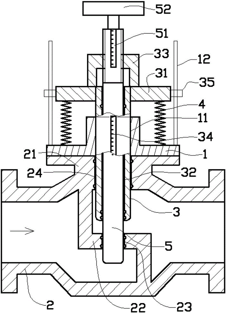
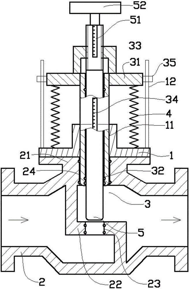
[0016] Such as figure 1 , figure 2 As shown in the embodiment, the pressure-visible pressure relief control regulating valve includes a fixedly connected upper valve body 1 and a lower valve body 2, and the lower valve body 2 is designed with three connection ports: a left port, a right port, and an upper port 21 , the middle of the lower valve body 2 is processed with a partition 22, and the partition 22 separates the cavity part connected by the left interface and the right interface into two independent cavities, and the position of the partition 22 below the upper interface 21 is Horizontal structure, the horizontal position of the partition 22 is designed with a water hole 23 facing the upper interface 21; it is characterized in that: the upper valve body 1 is designed with a vertical assembly hole 11, and the middle of the upper interface 21 A vertical sliding hole 24 is processe...


PUM


Abstract

The invention provides a pressure relief controlling regulating valve with pressure capable of being visible. The pressure relief controlling regulating valve comprises an upper valve body and a lower valve body, wherein the upper valve body and the lower valve body are fixedly connected; an isolation plate is arranged in the middle of lower valve body; a portion, connected with a left connecting opening and a right connecting opening, of a cavity is divided into two independent cavities by the isolation plate; the position, below an upper connecting opening of the lower valve body, of the isolation plate is of a horizontal structure; a water flowing hole facing the upper connecting opening directly is arranged on the horizontal position of the isolation plate; an outer pressure valve element capable of sliding up and down is installed inside an installing hole of the upper valve body; an inner regulating valve element is installed in the middle of the outer pressure valve element in a sliding and sealing mode; the water flowing hole is a cylindrical hole; the lower portion of the inner regulating valve element and the water flowing hole are assembled in a sliding and sealing mode; and the inner regulating valve element is connected with a pipe thread in a threaded mode. When the valve is in use, the water pressure inside the lower valve body can be convenient to observe for people through a lower scale of the outer pressure valve element. The quantity of pressure relief can be adjusted by adjusting the height of the inner regulating valve element.

Description

technical field [0001] The invention relates to the technical field of valves, in particular to a pressure-visual pressure relief control regulating valve. Background technique [0002] Valves can be used to control the on-off of flowing liquid. According to different control structures and control purposes, valves can be divided into many types. The pressure relief valve, also known as the safety valve, can automatically open and close according to the working pressure of the system, and is generally installed on the equipment or pipeline of the closed system to protect the safety of the system. When the pressure in the equipment or pipeline exceeds the set pressure of the pressure relief valve, it will automatically open the pressure relief to ensure that the medium pressure in the equipment and pipeline is below the set pressure, protect the equipment and pipeline, and prevent accidents. In many systems, the pressure in the pipeline can be observed in time, and a speci...

Claims


Application Information

Patent Timeline
Patent Type & Authority Applications(China)
IPC IPC(8): F16K17/06F16K37/00
CPCF16K17/044F16K17/046F16K37/0016F16K37/0091
Inventor 田洪卫
Owner SUZHOU KEDI FLUID CONTROL EQUIP
Why Eureka
Try Eureka