Forming device for crystal oscillator forming

A technology of crystal oscillators and shapers, applied in electrical components, impedance networks, etc., can solve problems such as difficulty

Inactive Publication Date: 2017-03-29
武汉昊昱微电子股份有限公司
View PDF3 Cites 0 Cited by
  • Summary
  • Abstract
  • Description
  • Claims
  • Application Information

AI Technical Summary

Problems solved by technology

For those components with small bodies, soft pins and deformed pins, it is difficult to use this forming method to meet customer requirements

Method used


Image

  • Forming device for crystal oscillator forming

Examples


Embodiment

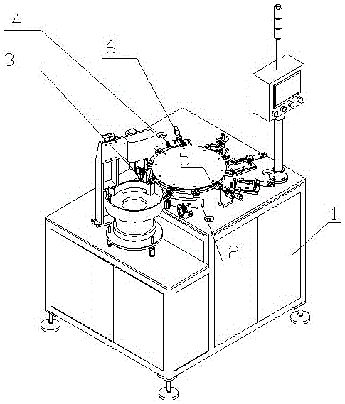
[0012] A forming device for forming a crystal oscillator is characterized in that it includes a frame 1, a conveying track 2 arranged on the frame 1, and a device arranged above the other end of the conveying track 2 for moving the crystal oscillator from the above-mentioned conveying track 2 The crystal oscillator suction nozzle 3 taken out, and the rotary table 4 arranged beside the crystal oscillator suction nozzle 3, the outer wall of the rotary table 4 is provided with a forming station for crystal oscillator forming in the circumferential direction. The forming station includes a crystal oscillator forming fixing key 5 arranged clockwise on the outer wall of the rotary table 4 and a shaper 6 arranged on the frame 1 to cooperate with the crystal oscillator forming fixing key 5 .

[0013] It also includes a discharge tray and a controller arranged on the side of the rotary table 4, and the controller is electrically connected with the driving device of the rotary table


PUM


Abstract

The present invention relates to a forming device, in particular, structural modification of a forming device for crystal oscillator forming. The forming device for crystal oscillator forming is characterized in that the forming device includes a rack (1), a conveying rail (2) arranged on the rack (1), a crystal oscillator suction nozzle (3) and a rotary workbench (4) which is arranged beside the crystal oscillator suction nozzle (3) , wherein the crystal oscillator suction nozzle (3) is arranged above one end of the conveying rail (2) and is used for taking out crystal oscillators from the conveying rail (2); and forming stations for crystal oscillator forming are arranged on the outer wall of the rotary worktable (4) along a circumferential direction. The forming device of the invention has the advantages of reasonable design, simple structure and great practicability. With the forming device of the present invention adopted, technical problems in the prior art can be solved. According to the forming device, component pins are not adopted to realize position limiting, and therefore, requirements for the component pins are not too high.

Description

technical field [0001] The invention relates to a forming device, in particular to an improvement on the structure of a forming device used for forming crystal oscillators. Background technique [0002] Vertical single-station forming is used in the forming of most electronic components such as LEDs, resistors, capacitors, and crystals. This forming method is suitable for components with larger bodies, thicker pins, and harder components. For those components with small bodies, soft pins and deformed pins, it is difficult to use this forming method to meet customer requirements. Contents of the invention [0003] The present invention mainly solves the technical problems existing in the prior art; it provides a forming device for forming crystal oscillators that does not use component pins for positioning, and therefore does not have too high requirements for component pins. [0004] Above-mentioned technical problem of the present invention is mainly solved by following ...

Claims


Application Information

Patent Timeline
Patent Type & Authority Applications(China)
IPC IPC(8): H03H3/02
Inventor 詹伟
Owner 武汉昊昱微电子股份有限公司
Why Eureka
Try Eureka