Transformer station electrical equipment dehumidifying apparatus

A technology for electrical equipment and substations, applied in the substation/distribution device shell, substation/switchgear cooling/ventilation, substation/switch arrangement details, etc., can solve the problem of dehumidification of electrical equipment, shortening service life, and susceptibility to moisture impact and other issues, to avoid operational safety and reduce air humidity

Inactive Publication Date: 2017-05-10
合肥普望电子有限责任公司
View PDF4 Cites 0 Cited by
  • Summary
  • Abstract
  • Description
  • Claims
  • Application Information

AI Technical Summary

Problems solved by technology

[0002] The dehumidification device is usually used in a humid environment. The dehumidification device completes dehumidification through the flow of air in it. According to whether cooling is performed during the dehumidification process, the dehumidifier uses cold water coils or cooling air to release part of the latent heat released during the dehumidification process. Go, inhibit the temperature rise of the dehumidification solution, improve the dehumidification efficiency, and the liquid dehumidification has continuous dehumidification, fast regeneration, can sterilize and wash the air, and can obtain stable dry air. Since the solution is in contact with the air in the form of mist, it is necessary to prevent the solution from being brought out or fly away; but the existing dehumidification device does not dehumidify the electrical equipment during dehumidification. During the use of the electrical equipment, it is easily affected by moisture and is easily damaged, which reduces the service life. In addition, the existing dehumidification device, its Simple structure, no dehumidification

Method used


Image

  • Transformer station electrical equipment dehumidifying apparatus

Examples


Embodiment Construction

[0011] The present invention will be further described below in conjunction with the accompanying drawings:

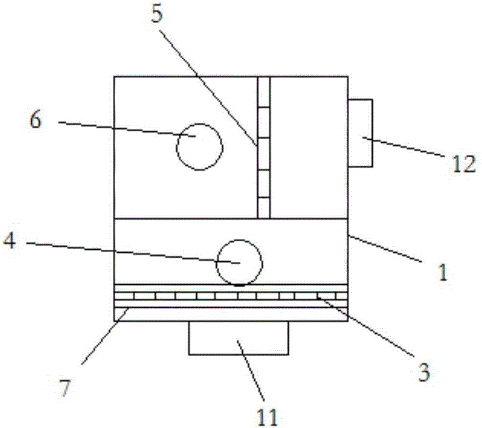
[0012] like figure 1 As shown, the dehumidification device for the electrical equipment of the substation in this embodiment includes a casing 1 and an air inlet 11 and an air outlet 12 arranged on the casing 1. The inner side of the air inlet 11 is provided with a condensing device 3 and an internal circulation fan 4. The air outlet 12 of the body 1 is provided with a heating device 5 and a double inlet centrifugal fan 6, the air inlet end of the inner circulation fan 4 is arranged opposite to the air inlet 11, and the air outlet end of the double inlet centrifugal fan 6 is opposite to the air outlet 12. The condensing device 3 is composed of a plurality of condensing fins superimposed on each other, and a plurality of ventilation holes are arranged on the condensing fins.

[0013] The heating device 5 is formed by stacking a plurality of heating sheets, and the stac...


PUM


Abstract

The invention relates to a transformer station electrical equipment dehumidifying apparatus. The apparatus comprises a housing and an air inlet and an air outlet which are arranged in the housing, wherein the inner side of the air inlet is provided with a condensing device and an internal circulation blower fan, the air outlet of the housing is provided with a heating device and a double-intake centrifugation blower fan, the air inlet end of the internal circulation blower fan is arranged to be opposite to the air inlet, the air outlet end of the double-intake centrifugation blower fan is arranged to be opposite to the air outlet, the condensing apparatus is formed by superposing multiple condensation sheets, and multiple air vents are arranged in the condensation sheets. According to the invention, through arrangement of the condensing device, water vapor in air is actively condensed to water droplets which flow out of the housing through a condensation water-collecting tray, such that air humidity inside an electronic part is reduced, and the operation safety is prevented from being affected by condensation of the water vapor on the surface of the electronic part.

Description

technical field [0001] The invention relates to a dehumidification device, in particular to a dehumidification device for electrical equipment in a substation. Background technique [0002] The dehumidifier is usually used in a humid environment. The dehumidifier completes the dehumidification in the flowing contact of the air. Depending on whether the dehumidification process is cooled or not, the dehumidifier uses a cold water coil or cooling air to release part of the latent heat released during the dehumidification process. The liquid dehumidification has the advantages of continuous dehumidification, fast regeneration, sterilization and air washing, and stable dry air can be obtained. Since the solution is in contact with the air in the form of a mist, it is necessary to prevent the solution from being carried out. or scattered; however, the existing dehumidifiers do not dehumidify electrical equipment during dehumidification, and the electrical equipment is easily affe...

Claims


Application Information

Patent Timeline
Patent Type & Authority Applications(China)
IPC IPC(8): H02B1/56H02B1/28
CPCH02B1/565H02B1/28
Inventor 顾孙珺孙平陆华俊孙国庆
Owner 合肥普望电子有限责任公司
Why Eureka
Try Eureka