Solder paste stirring equipment used in electronic product manufacturing

A technology for electronic products and stirring equipment, which is used in mixer accessories, mixers with rotary stirring devices, and dissolution, and can solve the problems of low stirring efficiency and complicated operation.

Inactive Publication Date: 2017-06-30
苍南博雅科技有限公司
View PDF0 Cites 7 Cited by
  • Summary
  • Abstract
  • Description
  • Claims
  • Application Information

AI Technical Summary

Problems solved by technology

[0005] In order to overcome the shortcomings of the current mixing equipment such as relatively low stirring efficiency, complex operation, and the need for manual stirring with a stirring rod, the technical problem to be solved by the present invention is to provide a stirring rod that does not need to be manually held by hand, and has simple operation and high stirring efficiency. Tall solder paste mixing equipment for electronics manufacturing

Method used


Image

  • Solder paste stirring equipment used in electronic product manufacturing
  • Solder paste stirring equipment used in electronic product manufacturing
  • Solder paste stirring equipment used in electronic product manufacturing

Examples


Embodiment 1

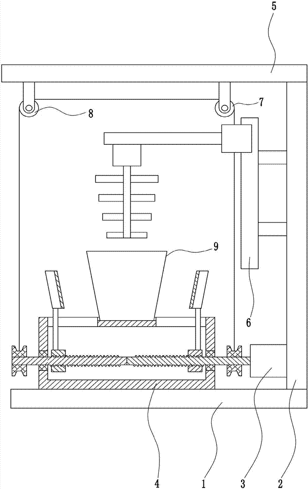
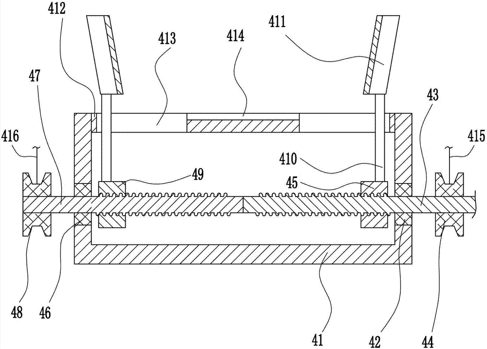
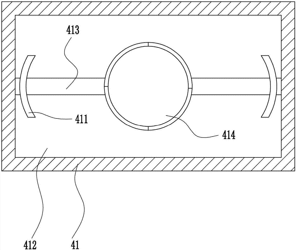
[0030] A solder paste mixing equipment used in the manufacture of electronic products, such as Figure 1-5 As shown, it includes a bottom plate 1, a right frame 2, a first motor 3, a clamping mechanism 4, a top plate 5, a stirring mechanism 6, a first fixed pulley 7 and a second fixed pulley 8, and the right frame 2 is installed on the top right end of the bottom plate 1. , the bottom of the left side of the right frame 2 is equipped with a first motor 3, the top of the bottom plate 1 is equipped with a clamping mechanism 4, the clamping mechanism 4 is connected with the left side of the first motor 3, and the upper left side of the right frame 2 is equipped with a stirring mechanism 6, The top of the right frame 2 is connected with a top plate 5, a first fixed pulley 7 is installed on the right side of the bottom of the top plate 5, a second fixed pulley 8 is installed on the left side of the bottom of the top plate 5, and the solder paste bucket 9 can be placed on the clampin...

Embodiment 2

[0032] A solder paste mixing equipment used in the manufacture of electronic products, such as Figure 1-5 As shown, it includes a bottom plate 1, a right frame 2, a first motor 3, a clamping mechanism 4, a top plate 5, a stirring mechanism 6, a first fixed pulley 7 and a second fixed pulley 8, and the right frame 2 is installed on the top right end of the bottom plate 1. , the bottom of the left side of the right frame 2 is equipped with a first motor 3, the top of the bottom plate 1 is equipped with a clamping mechanism 4, the clamping mechanism 4 is connected with the left side of the first motor 3, and the upper left side of the right frame 2 is equipped with a stirring mechanism 6, The top of the right frame 2 is connected with a top plate 5, a first fixed pulley 7 is installed on the right side of the bottom of the top plate 5, a second fixed pulley 8 is installed on the left side of the bottom of the top plate 5, and the solder paste bucket 9 can be placed on the clampin...

Embodiment 3

[0035] A solder paste mixing equipment used in the manufacture of electronic products, such as Figure 1-5 As shown, it includes a bottom plate 1, a right frame 2, a first motor 3, a clamping mechanism 4, a top plate 5, a stirring mechanism 6, a first fixed pulley 7 and a second fixed pulley 8, and the right frame 2 is installed on the top right end of the bottom plate 1. , the bottom of the left side of the right frame 2 is equipped with a first motor 3, the top of the bottom plate 1 is equipped with a clamping mechanism 4, the clamping mechanism 4 is connected with the left side of the first motor 3, and the upper left side of the right frame 2 is equipped with a stirring mechanism 6, The top of the right frame 2 is connected with a top plate 5, a first fixed pulley 7 is installed on the right side of the bottom of the top plate 5, a second fixed pulley 8 is installed on the left side of the bottom of the top plate 5, and the solder paste bucket 9 can be placed on the clampin...


PUM


Abstract

The invention relates to stirring equipment, in particular to solder paste equipment used in electronic product manufacturing. The technical purpose is to provide the solder paste equipment which is used for electronic product manufacturing, saves the troubles of people conducting manual stirring with a stirring rod in hand, and is simple in operation and high in stirring efficiency. The solder paste equipment used in electronic product manufacturing comprises a base plate, a right frame, a first motor, a clamping mechanism, a top plate, a stirring mechanism and the like; the right end of the top of the base plate is provided with the right frame, the bottom end of the left side of the right frame is provided with the first motor, the top of the base plate is provided with the clamping mechanism, the clamping mechanism is connected to the left side of the first motor, the upper portion of the left side of the right frame is provided with the stirring mechanism, and the top end of the right frame is connected to the top plate. According to the solder paste equipment used in electronic product manufacturing, the first motor is utilized to drive the clamping mechanism to clamp a solder paste bucket, and the clamping mechanism is utilized to drive the stirring mechanism to move downwards at the same time; meanwhile, travel switches are further installed at the upper and lower ends of the left side of a slide rail.

Description

technical field [0001] The invention relates to a stirring device, in particular to a solder paste stirring device used in the manufacture of electronic products. Background technique [0002] Solder paste is also called solder paste, the English name is solderpaste, gray paste. Solder paste is a new type of soldering material that emerged with SMT. It is a paste mixture formed by mixing solder powder, flux, and other surfactants and thixotropic agents. It is mainly used for soldering electronic components such as PCB surface resistance, capacitor and IC in SMT industry. [0003] Electronic products need to be stirred before solder paste is used in the manufacture of electronic products. The current mixing equipment is relatively inefficient and complicated to operate, requiring manual stirring with a stirring rod. Efficient solder paste mixing equipment for electronics manufacturing. Contents of the invention [0004] (1) Technical problems to be solved [0005] In or...

Claims


Application Information

Patent Timeline
Patent Type & Authority Applications(China)
IPC IPC(8): B01F7/18B01F15/00
CPCB01F27/806B01F27/90B01F35/30B01F35/34B01F35/42
Inventor 杨连数
Owner 苍南博雅科技有限公司
Why Eureka
Try Eureka