Trigger switch structure, shell structure of electronic equipment, and electronic equipment

A technology for triggering switches and housing structures, which is applied to electrical equipment housings/cabinets/drawers, housings with display/control units, electrical components, etc., which can solve problems affecting the normal use of electronic equipment and reduce the strength of the frame, and achieve The effect of reducing space occupation, avoiding over-processing, and high structural strength

Active Publication Date: 2017-07-04
XIAOMI INC
View PDF6 Cites 0 Cited by
  • Summary
  • Abstract
  • Description
  • Claims
  • Application Information

AI Technical Summary

Problems solved by technology

Based on the above structural requirements, the internal structural components of electronic equipment also need to be improved accordingly. For example, when the trigger switch and related structures in related technologies are continued to be used, the frame strength of electronic equipment will be seriously reduced, and even affect the normal use of electronic equipment.

Method used


Image

  • Trigger switch structure, shell structure of electronic equipment, and electronic equipment
  • Trigger switch structure, shell structure of electronic equipment, and electronic equipment
  • Trigger switch structure, shell structure of electronic equipment, and electronic equipment

Examples


Embodiment Construction

[0027] Reference will now be made in detail to the exemplary embodiments, examples of which are illustrated in the accompanying drawings. When the following description refers to the accompanying drawings, the same numerals in different drawings refer to the same or similar elements unless otherwise indicated. The implementations described in the following exemplary examples do not represent all implementations consistent with the present disclosure. Rather, they are merely examples of apparatuses and methods consistent with aspects of the present disclosure as recited in the appended claims.

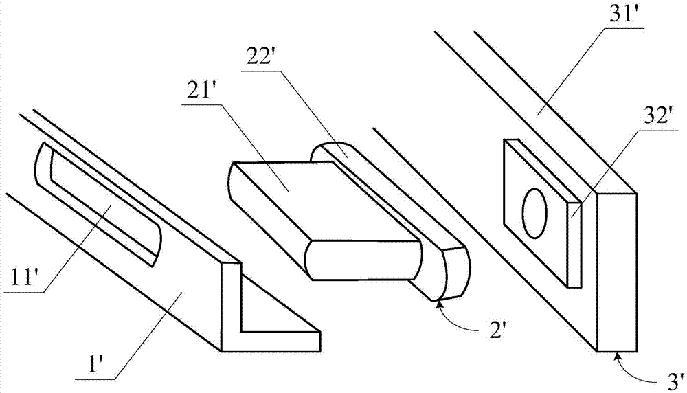
[0028] figure 1 It is a schematic diagram of the housing structure, button structure and trigger switch structure of electronic equipment in the related art, such as figure 1 As shown, in the related art, a through hole 11' is provided on the side wall of the shell structure 1' of the electronic device, and the key structure 2' of the electronic device includes a keycap 21' and a base...


PUM


Abstract

The invention discloses a trigger switch structure, a shell structure of electronic equipment, and the electronic equipment. The trigger switch structure can comprise a circuit board, wherein a connector, which is connected to a main board on the electronic equipment, extends from the inner side of the circuit board; a plurality of bumps are formed on the outer side of the circuit board; a corresponding trigger switch is arranged on the surface of each bump, wherein the bumps are bent downwardly to be perpendicular to the circuit board; and therefore, when the circuit board is pasted on the top side of a frame of the shell structure of the electronic equipment, the bumps can be inserted into a preset cavity in the frame through openings in the top side of the frame, so as to enable keys which extend in the preset cavity to be matched with the corresponding trigger switches on the bumps. By virtue of the technical scheme disclosed by the invention, the trigger switch structure can be matched with narrow frames of the electronic equipment, and excessive influence to the strength of the frame structure can be avoided.

Description

technical field [0001] The present disclosure relates to the technical field of terminals, and in particular to a trigger switch structure, a shell structure of an electronic device, and the electronic device. Background technique [0002] At present, electronic devices are becoming more and more thin and differentiated. For example, electronic devices are required to be thinner, have narrower frames, and have larger screen-to-body ratios. Based on the above structural requirements, the internal structural components of the electronic equipment also need to be improved accordingly. For example, if the trigger switch and related structures in the related art are continued to be used, the frame strength of the electronic equipment will be severely reduced, and even the normal use of the electronic equipment will be affected. Contents of the invention [0003] The disclosure provides a trigger switch structure, a casing structure of an electronic device and the electronic dev...

Claims


Application Information

Patent Timeline
Patent Type & Authority Applications(China)
IPC IPC(8): H05K5/00
CPCH05K5/0017
Inventor 张斌韩高才高原
Owner XIAOMI INC
Why Eureka
Try Eureka