Electrical connectors for circuit boards

A technology of circuit substrates and electrical connectors, which is applied in the direction of connection, circuit, and parts of connection devices, etc., to achieve a large floating amount, increase the floating amount, and ensure the effect of elastic deformation

Active Publication Date: 2019-07-26
HIROSE ELECTRIC GROUP
View PDF7 Cites 0 Cited by
  • Summary
  • Abstract
  • Description
  • Claims
  • Application Information

AI Technical Summary

Problems solved by technology

[0008] In the above-mentioned terminal of the electrical connector for circuit board of Patent Document 1, the above-mentioned movable part that can float is formed in a substantially ring shape, so if the height direction of the connector (the direction perpendicular to the board surface of the circuit board) or the width direction ( If the floating amount is also increased in the horizontal direction parallel to the board surface of the circuit board, the movable part must be increased in these directions, resulting in an increase in the size of the connector in this direction

Method used


Image

  • Electrical connectors for circuit boards
  • Electrical connectors for circuit boards
  • Electrical connectors for circuit boards

Examples


Embodiment Construction

[0027] Embodiments of the present invention will be described below based on the drawings.

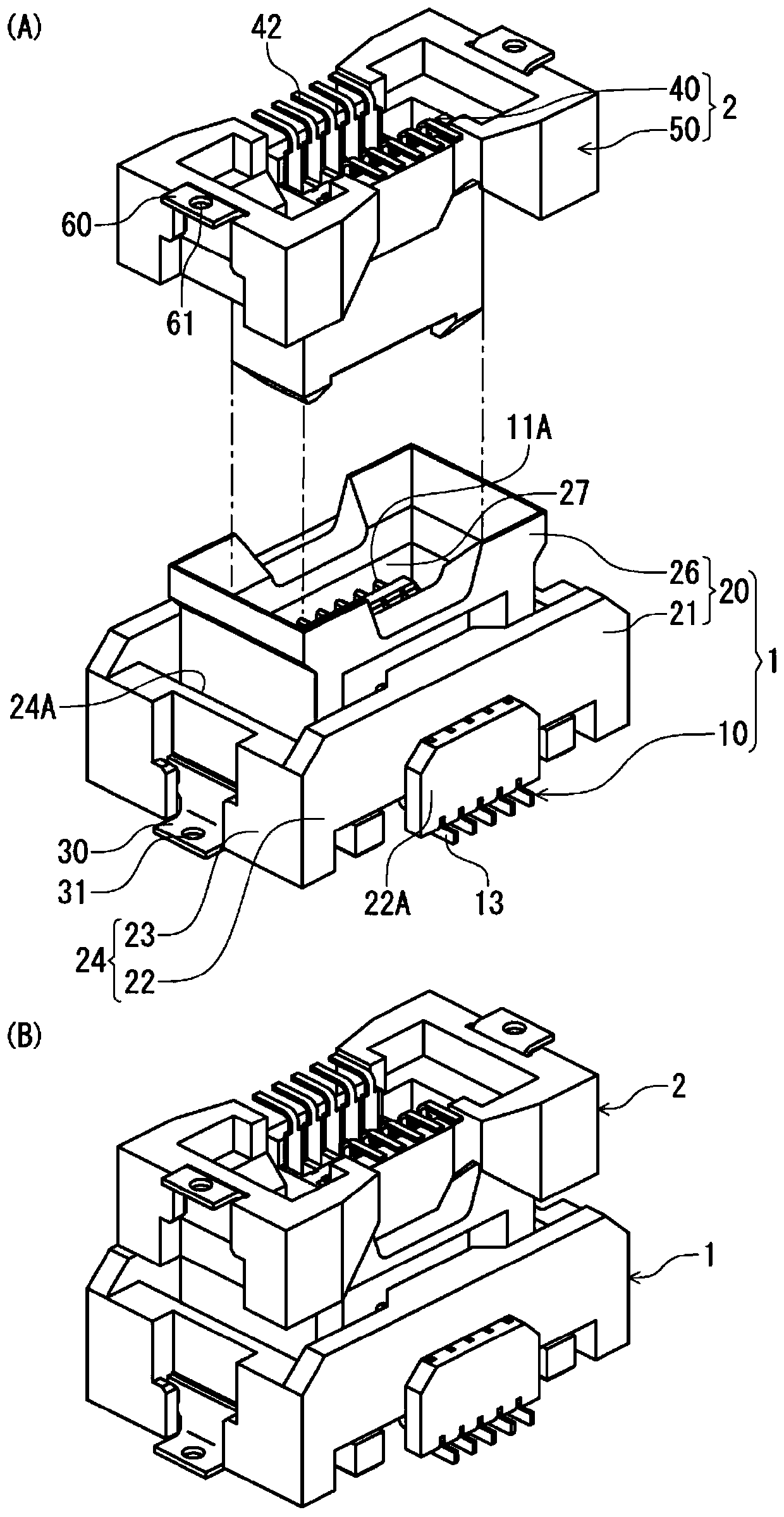
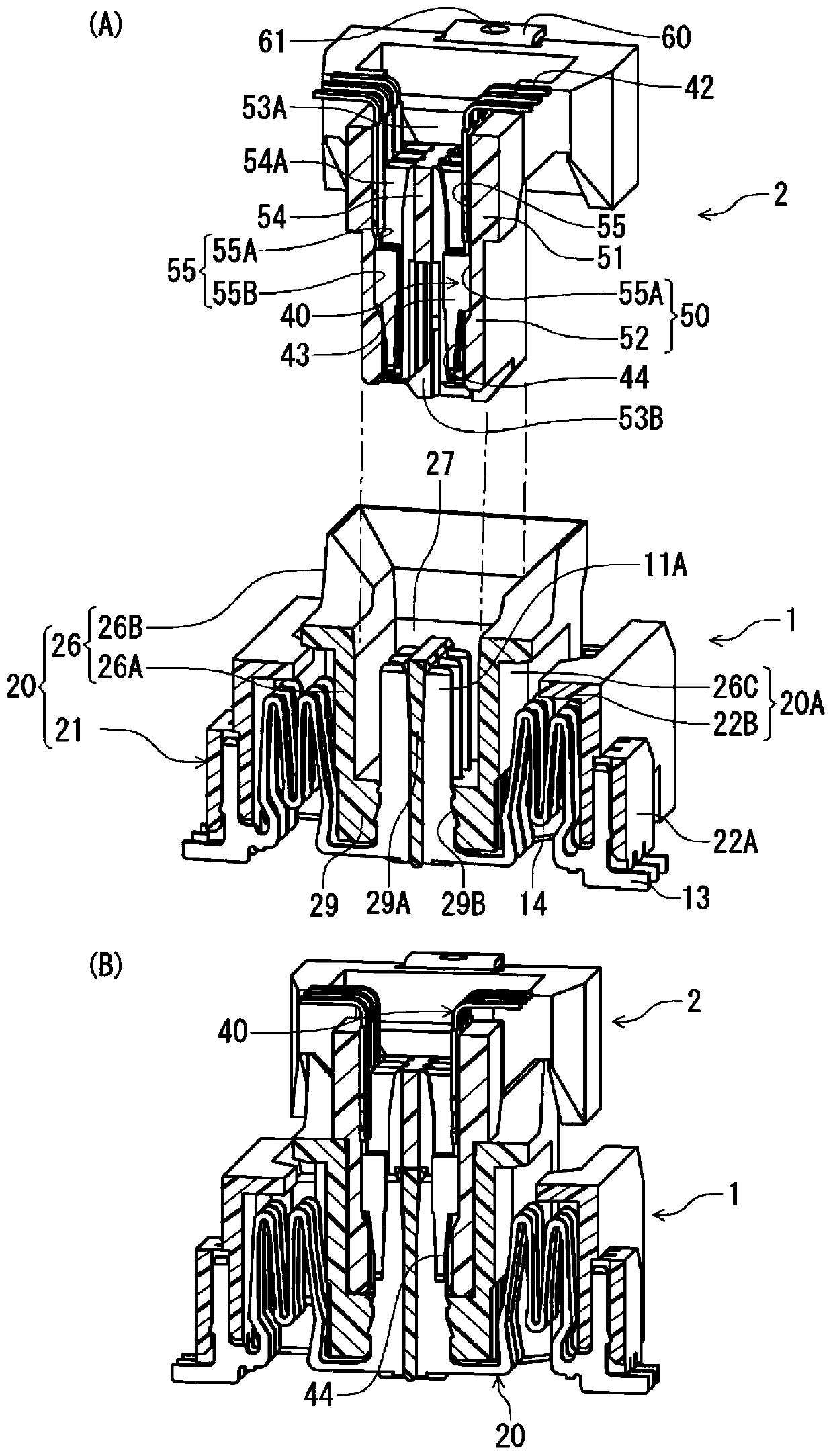
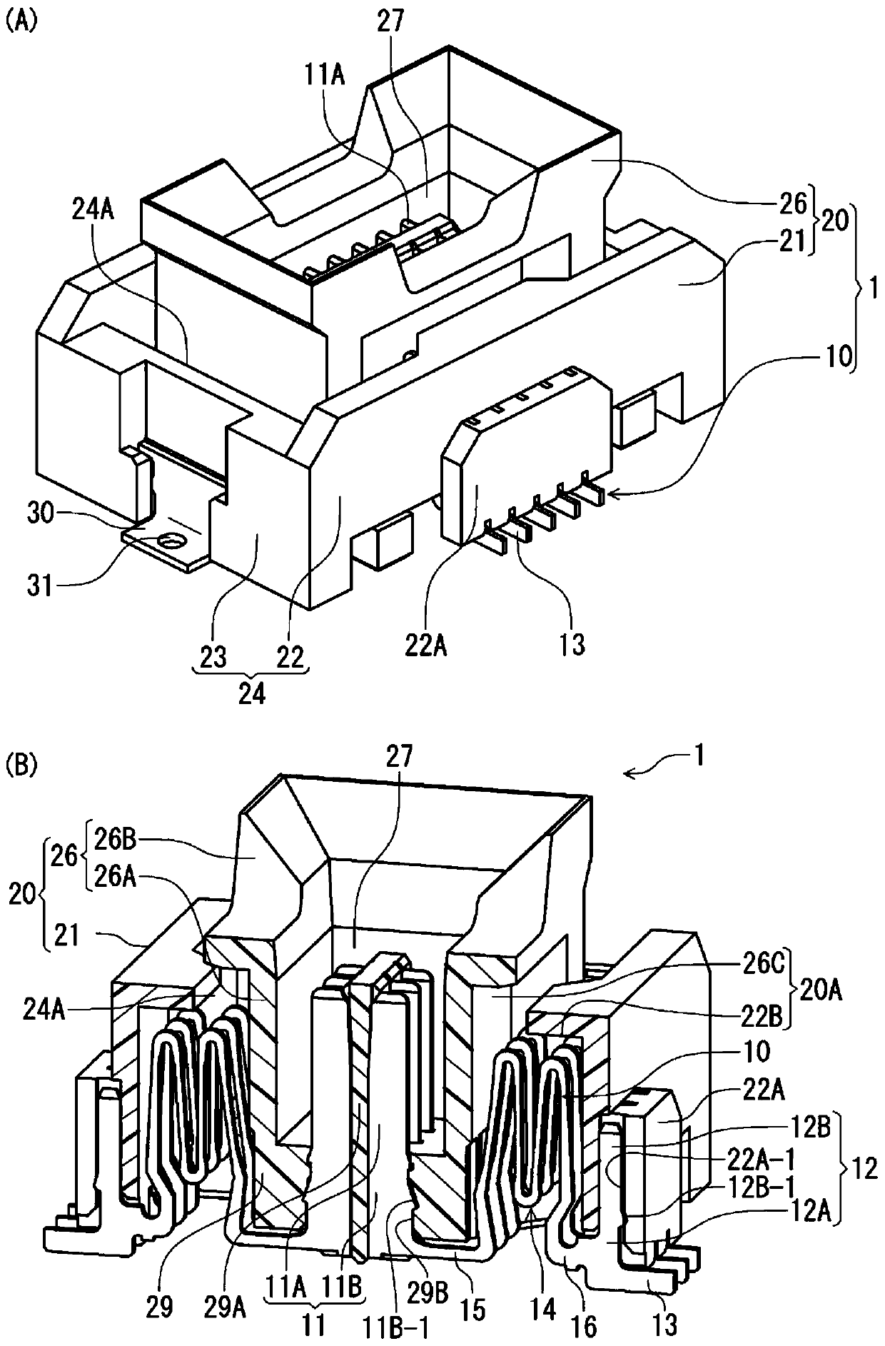
[0028] figure 1It is a connector assembly including a plug-side connector (hereinafter referred to as "first connector") and a receptacle-side connector (hereinafter referred to as "second connector") fitted and connected thereto as one embodiment of the present invention. , figure 1 (A) is an appearance perspective view showing a state before fitting connection, figure 1 (B) is an external perspective view showing a state after fitting connection. Here, the plug side refers to the side having the male terminal, and the receptacle side refers to the side having the female terminal fitted to the male terminal. in addition, figure 2 is to show figure 1 A cut-away perspective view of the interior of the two connectors, figure 2 (A) shows the corresponding figure 1 (A) The state before the chimera connection, figure 2 (B) shows the corresponding figure 1 (B) The state after chi...


PUM


Abstract

An electrical connector includes a terminal having a connecting portion to be connected to an electrical circuit board and a contact portion to be contacted with a mating connector; and a housing for holding the terminal. The housing includes a fixed housing and a movable housing arranged to be movable relative to the fixed housing. The terminal includes a fixed side held portion held with the fixed housing, a movable side held portion held with the movable housing, and an elastic portion situated between the fixed side held portion and the movable side held portion. The housing includes an accommodating space for accommodating the elastic portion. The elastic portion includes a first wave shape portion having a first bent portion and a pair of first extending portions. The first extending portions are configured to extend away from each other with a distance in between decreasing toward the first bent portion.

Description

technical field [0001] The present invention relates to an electrical connector for a circuit board in which a mating connection body is connected to a surface of the circuit board in a direction perpendicular to the surface of the circuit board in a state mounted on the circuit board. Background technique [0002] As such an electrical connector for a circuit board, Patent Document 1 discloses a connector including a fixed case for fixing a case for holding terminals to the circuit board, and a fixed case for moving relative to the fixed case. The movable casing, and the terminals are bridged between the fixed casing and the movable casing. [0003] The fixed housing mounted on the surface of the circuit board of the connector of this patent document 1 is formed in a square frame shape, and the central part of the interior is opened to penetrate up and down, and the movable housing is arranged in the central part. A space is formed around the body and between the movable c...

Claims


Application Information

Patent Timeline
Patent Type & Authority Patents(China)
IPC IPC(8): H01R12/71H01R13/05H01R13/24H01R13/631
CPCH01R12/716H01R13/05H01R13/2428H01R13/2471H01R13/6315H01R12/707H01R12/712H01R12/91H01R13/502H01R12/7005
Inventor 土井健太郎
Owner HIROSE ELECTRIC GROUP
Why Eureka
Try Eureka