

Error diagnostic detection method for accelerometer
A technology of accelerometer and detection method, applied in the direction of speed/acceleration/shock measurement, testing/calibration of speed/acceleration/shock measurement equipment, measurement device, etc., can solve problems such as high cost and low efficiency
- Summary
- Abstract
- Description
- Claims
- Application Information
AI Technical Summary
Problems solved by technology
Method used
Image

Examples
Embodiment 1
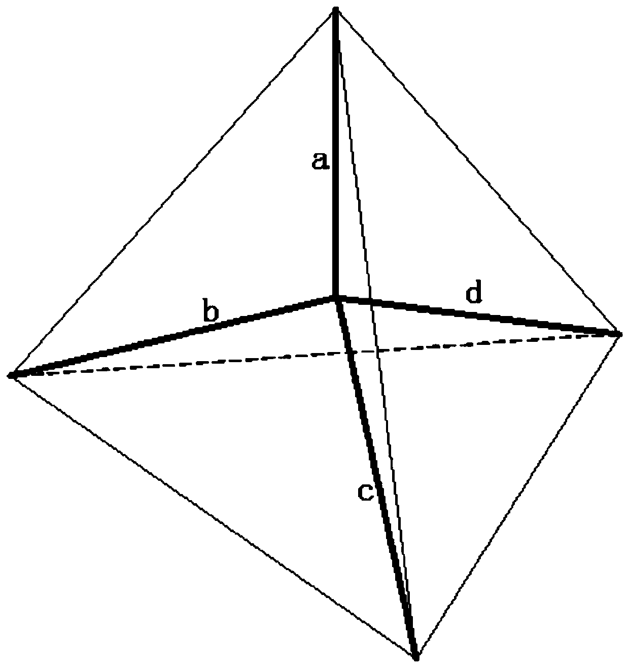
[0027] A method for error diagnosis and detection of an accelerometer in a three-dimensional space, the specific steps of which are as follows:
[0028] (1): Use the center of the regular tetrahedron and each end point to form a non-orthogonal four-axis (a, b, c, d); use the center of gravity as the starting point to obtain the vector data of a, b, c, and d;
[0029] (2): Taking a as a benchmark, perform vector decomposition on b, c, and d, and obtain the vector value on the straight line where the axis a is located;
[0030] (3): Calculate the vector sum of b, c, and d in the direction of axis a, and compare it with the actual measurement a;
[0031] (4): If it matches, the result is feasible, if it does not match, the result is not credible;
[0032] (5): A series of consecutive data results are unreliable, that is, the diagnosis and detection device fails, an error indication is issued, and the system is prompted to replace or scrap the device.
Embodiment 2
[0034] A method for error diagnosis and detection of an accelerometer in a three-dimensional space, the specific steps of which are as follows:
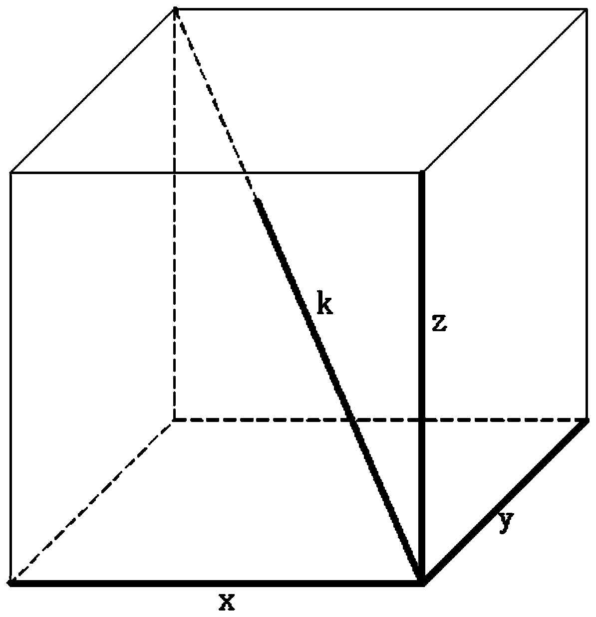
[0035] (1): Use a cube to connect three sides and a pair of fixed points to form a local non-orthogonal four-axis (x, y, z, k); take the pair of fixed points as the starting point to obtain the vector data of (x, y, z, k);
[0036] (2): With k as a benchmark, vector decomposition is performed on x, y, and z to obtain the vector value on the straight line where the axis k is located;
[0037] (3): Calculate the vector sum of x, y, z in the direction of axis k, and compare it with the actual measurement k;
[0038] (4): If it matches, the result is feasible, if it does not match, the result is not credible;
[0039] (5): A series of consecutive data results are unreliable, that is, the diagnosis and detection device fails, an error indication is issued, and the system is prompted to replace or scrap the device.
Embodiment 3
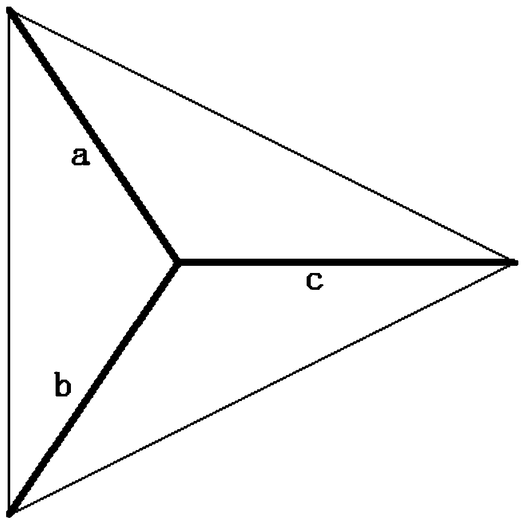
[0041] A method for error diagnosis and detection of an accelerometer in a two-dimensional space, the specific steps of which are as follows:
[0042] (1): Use the non-orthogonal three axes (a, b, c) formed by the center of the equilateral triangle and each end point to obtain the vector data of a, b, and c;
[0043] (2): Taking a as a benchmark, perform vector decomposition on b and c, and obtain the vector value on the straight line where the axis a is located;
[0044] (3): Calculate the vector sum of b and c in the direction of axis a, and compare it with the actual measurement of a;
[0045] (4): If it matches, the result is feasible, if it does not match, the result is not credible;
[0046] (5): A series of consecutive data results are unreliable, that is, the diagnosis and detection device fails, an error indication is issued, and the system is prompted to replace or scrap the device.
PUM
 Abstract
Description
Claims
Application Information