Industrial continuous ore crushing device

A crushing device, industrial technology, applied in solid separation, filter screen, grid, etc., can solve the problems of difficult maintenance, large volume, difficult to move, etc.

Inactive Publication Date: 2017-09-01
李翔
View PDF4 Cites 56 Cited by
  • Summary
  • Abstract
  • Description
  • Claims
  • Application Information

AI Technical Summary

Problems solved by technology

[0006] In order to overcome the current shortcomings of large volume, difficult movement and maintenance, the technical problem to be solved by the present inventi

Method used


Image

  • Industrial continuous ore crushing device
  • Industrial continuous ore crushing device

Examples


Embodiment 1

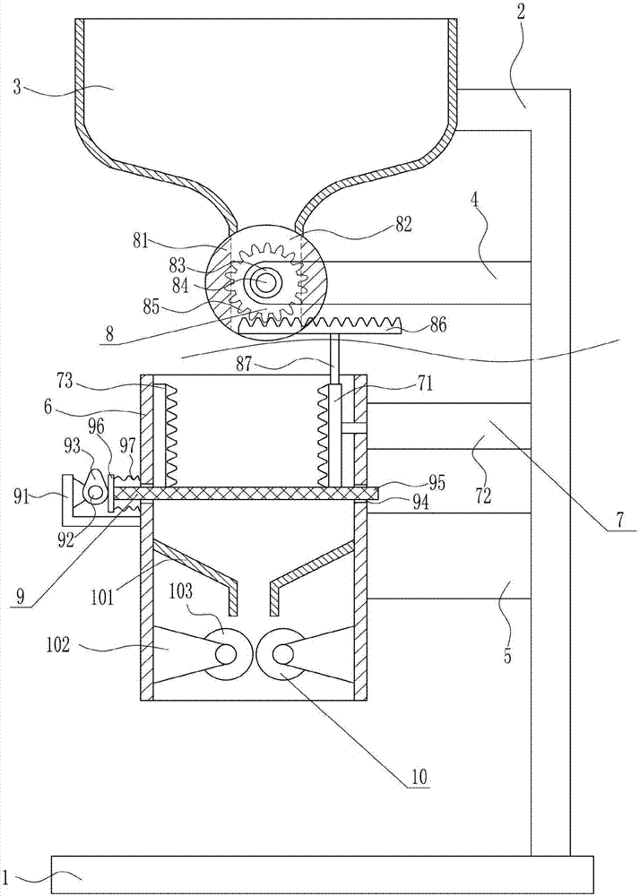
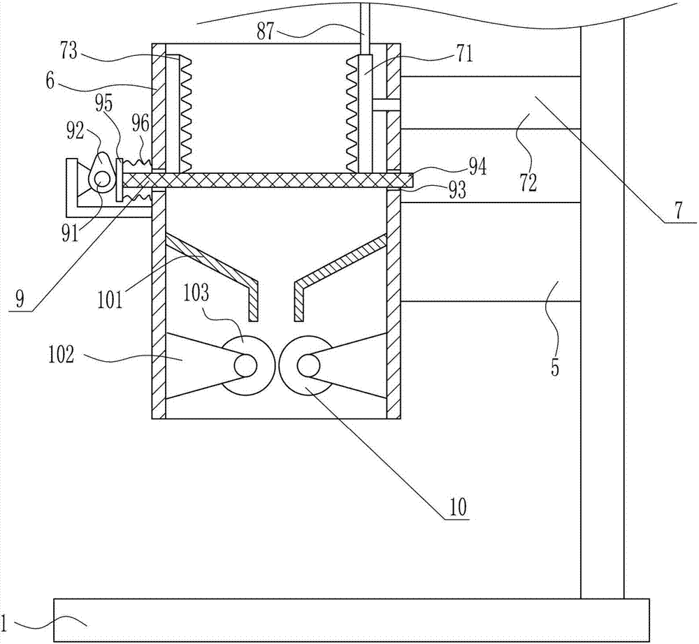
[0027] An industrial ore continuous crushing device, such as Figure 1-2 As shown, it includes a bottom plate 1, an L-shaped bracket 2, a feed hopper 3, a first pole 4, a second pole 5, a crushing cylinder 6, a crushing device 7, a feeding device 8, a screening device 9 and a crushing device 10 The right side of the top of the bottom plate 1 is connected with an L-shaped bracket 2 by means of bolt connection, the top of the L-shaped bracket 2 is provided with a feed hopper 3, and the inner side of the L-shaped bracket 2 is provided with a first pole 4 and a second pole 5, the second A rod 4 is located above the second rod 5, the left end of the first rod 4 is provided with a feeding device 8, and a crushing tube 6 is provided directly below the feeding device 8, and the right end of the crushing tube 6 is connected to the second rod. The left end of 5 is connected, and the crushing device 7 is arranged on the inner upper part of the crushing cylinder 6, and the screening devic...

Embodiment 2

[0029] An industrial ore continuous crushing device, such as Figure 1-2 As shown, it includes a bottom plate 1, an L-shaped bracket 2, a feed hopper 3, a first pole 4, a second pole 5, a crushing cylinder 6, a crushing device 7, a feeding device 8, a screening device 9 and a crushing device 10 The right side of the top of the bottom plate 1 is connected with an L-shaped bracket 2 by means of bolt connection, the top of the L-shaped bracket 2 is provided with a feed hopper 3, and the inner side of the L-shaped bracket 2 is provided with a first pole 4 and a second pole 5, the second A rod 4 is located above the second rod 5, the left end of the first rod 4 is provided with a feeding device 8, and a crushing tube 6 is provided directly below the feeding device 8, and the right end of the crushing tube 6 is connected to the second rod. The left end of 5 is connected, and the crushing device 7 is arranged on the inner upper part of the crushing cylinder 6, and the screening devic...

Embodiment 3

[0032] An industrial ore continuous crushing device, such as Figure 1-2As shown, it includes a bottom plate 1, an L-shaped bracket 2, a feed hopper 3, a first pole 4, a second pole 5, a crushing cylinder 6, a crushing device 7, a feeding device 8, a screening device 9 and a crushing device 10 The right side of the top of the bottom plate 1 is connected with an L-shaped bracket 2 by means of bolt connection, the top of the L-shaped bracket 2 is provided with a feed hopper 3, and the inner side of the L-shaped bracket 2 is provided with a first pole 4 and a second pole 5, the second A rod 4 is located above the second rod 5, the left end of the first rod 4 is provided with a feeding device 8, and a crushing tube 6 is provided directly below the feeding device 8, and the right end of the crushing tube 6 is connected to the second rod. The left end of 5 is connected, and the crushing device 7 is arranged on the inner upper part of the crushing cylinder 6, and the screening device...


PUM


Abstract

The invention relates to an ore crushing device, in particular to an industrial continuous ore crushing device, and aims at achieving the technical purpose of providing an industrial continuous ore crushing device which is continuous and reliable in work, convenient to maintain and repair and high in ore crushing efficiency. In order to achieve the technical purpose, the industrial continuous ore crushing device comprises a bottom plate, an L-shaped support, a feeding hopper, a first support rod, a second support rod, a crushing barrel and the like; the L-shaped support is connected to the right side of the top of the bottom plate in a bolt connection mode, the feeding hopper is arranged at the top end of the L-shaped support, the first support rod and the second support rod are arranged on the inner side of the L-shaped support, the first support rod is located over the second support rod, a discharging device is arranged at the left end of the first support rod, and the crushing barrel is arranged under the discharging device. According to the industrial continuous ore crushing device, when ore is crushed, the effects of being continuous and reliable in work, convenient to maintain and repair and high in ore crushing efficiency are achieved.

Description

technical field [0001] The invention relates to an ore crushing device, in particular to an industrial ore continuous crushing device. Background technique [0002] Ore refers to mineral aggregates from which useful components can be extracted or which have certain properties that can be utilized. It can be divided into metallic minerals and non-metallic minerals. The unit content of useful components (elements or minerals) in ores is called ore grade. Precious metal ores such as gold and platinum are expressed in grams per ton, and other ores are usually expressed in percentages. The ore grade is often used to measure the value of ore, but the composition and harmful impurities of the gangue (useless minerals in the ore or minerals with very little useful content that cannot be used) and harmful impurities in the ore also affect the value of the ore. [0003] A pulverizer is a machine that crushes large-sized solid raw materials into required sizes. The pulverizer is com...

Claims


Application Information

Patent Timeline
IPC IPC(8): B02C21/00B02C1/00B02C23/02B02C4/02B02C23/10B07B1/30B07B1/42
CPCB02C21/00B02C1/005B02C4/02B02C23/02B02C23/10B07B1/30B07B1/42
Inventor 李翔
Owner 李翔
Why Eureka
Try Eureka