

Display method of display device and display device
A display device and display panel technology, applied to static indicators, instruments, etc., can solve problems such as abnormal display and abnormal signal
- Summary
- Abstract
- Description
- Claims
- Application Information
AI Technical Summary
Problems solved by technology
Method used
Image

Examples
Embodiment 1
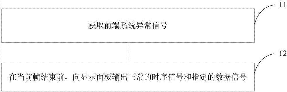
[0035] figure 2 It is a flowchart of a display method of a display device according to an embodiment of the present invention, such as figure 2 As shown, the method of the present embodiment includes:
[0036] Step 11, obtaining the abnormal signal of the front-end system;
[0037] Step 12. Before the end of the current frame, output normal timing signals and designated data signals to the display panel.
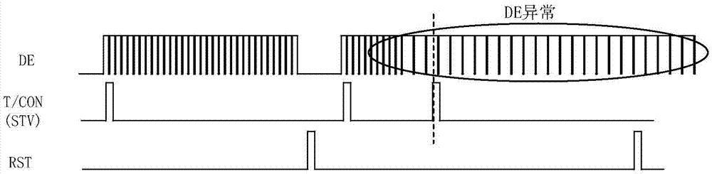
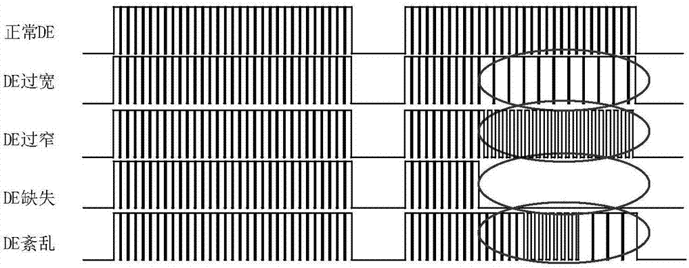
[0038] In this embodiment, the timing controller can obtain the front-end signal abnormality by analyzing the effective data strobe signal, and the effective data strobe signal usually has an abnormality, such as image 3 Shown: The frequency of the effective data strobe signal is too high or too small, the effective data strobe signal is missing, and the frequency of the effective data strobe signal is unstable.
[0039] The method for detecting the abnormality of the effective data strobe signal includes: first, the timing controller extracts the effective data strobe...
Embodiment 2
[0043] Figure 5 It is a flow chart of a display control method in this embodiment.
[0044] Among them, flag1 is an abnormal mark of the valid data strobe signal, and flag1=1 indicates that the valid data strobe signal is abnormal;
[0045] flag2 is the abnormal response flag bit, flag2=1 indicates that the front-end system signal is abnormal;
[0046] flag3 is the frame end flag, which is automatically recognized by the timing controller, flag3=1 means the end of the current frame;
[0047] Flag4 is a flag bit for abnormal recovery preparation, flag4=1 means that the current end system signal returns to normal;
[0048] flag5 is the frame start flag, by reading the start bit data sent by the front-end system to the timing controller, determine the state of the frame start flag, where flag5=1 means that the system starts to send the current frame display data;
[0049]flag6 is a normal display flag, and flag6=1 indicates that the front-end system signal is normal.
[0050...
Embodiment 3
[0061] Figure 7 It is a flowchart of a display control method in this embodiment, such as Figure 7 As shown, the method of the present embodiment includes:
[0062] Step 31, the timing controller obtains the abnormal signal of the front-end system;
[0063] Step 32. Before the end of the current frame, the timing controller continues to output normal timing signals to the display panel, and triggers the data driver to output specified data signals to the display panel;
[0064] Step 33, the sequence controller triggers the display panel to enter the failure mode after the end of the frame when the abnormal signal of the front-end system is obtained, that is, the sequence controller sends the normal sequence to the display panel and sends black picture data to the display panel.
[0065] Step 34. The timing controller receives the signal that the front-end system signal is restored to normal. If the frame corresponding to the signal that the front-end system signal is resto...
PUM
 Abstract
Description
Claims
Application Information