Touch display equipment

A touch display and equipment technology, which is applied to instruments, electrical digital data processing, and data processing input/output processes, etc., and can solve problems such as color difference between non-visual areas and visible areas.

Active Publication Date: 2017-11-10
TPK ADVANCED SOLUTIONS
View PDF6 Cites 1 Cited by
  • Summary
  • Abstract
  • Description
  • Claims
  • Application Information

AI Technical Summary

Problems solved by technology

However, since the black matrix system is black, and display panels such as liquid crystal panels or organic light-emitting diode panels are often not black when they are turned off, when this type of touch display device is not in use, the non-visible area and The junction of the visible area will be quite obvious, that is, there will be obvious color difference between the non-visible area and the visible area

Method used


Image

  • Touch display equipment
  • Touch display equipment
  • Touch display equipment

Examples


Embodiment Construction

[0031] The present invention will be further described in detail below in conjunction with the accompanying drawings and specific embodiments.

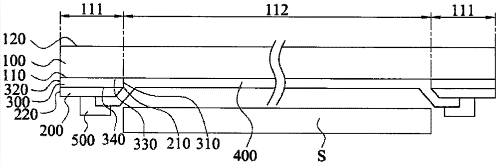
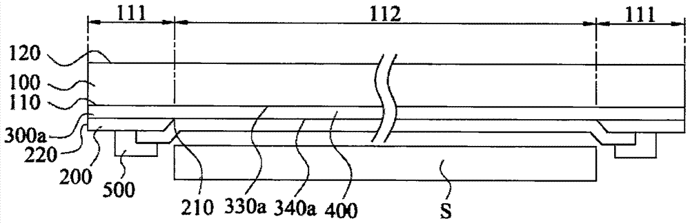
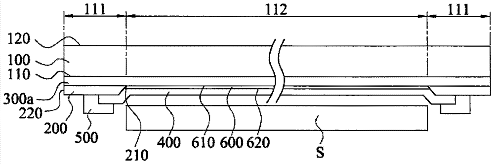
[0032] figure 1 A cross-sectional view of a touch display device according to an embodiment of the present invention is shown. Such as figure 1 As shown, in this embodiment, the touch display device may include a transparent cover 100 , a light-shielding layer 200 , a toning layer 300 and a touch-sensitive layer 400 . The transparent cover 100 has an inner surface 110 . The transparent cover 100 is divided into a first area 111 and a second area 112 . The first area 111 is adjacent to the second area 112 . In some embodiments, the first area 111 can be an annular area and surround the second area 112 . The light-shielding layer 200 is disposed on the first area 111 of the inner surface 110 and is not located on the second area 112, so that the first area 111 can be used as a non-visible area of ​​the touch display device, and the...


PUM


Abstract

The invention provides touch display equipment. The touch display equipment comprises a transmitting cover plate, a shading layer, a touch induction layer and a color modulation layer, wherein the transmitting cover plate is provided with an inner surface; the inner surface is divided into a first region and a second region; the shading layer is arranged in the first region and not located in the second region of the inner surface; and the color modulation layer is located between the shading layer and the transmitting cover plate, so that the chromatic aberration between the first region and the second region is smaller than or equal to 3 when the touch display equipment is in a non-use state. Through the touch display equipment, the color difference between a visual region and a non-visual region can be lowered and even eliminated, and therefore the visibility of a boundary between the visual region and the non-visual region is lowered.

Description

technical field [0001] The invention relates to a touch display device. Background technique [0002] In the touch display device, the touch panel can cover the display panel, so the user can touch the corresponding position of the touch panel corresponding to the display pattern on the display panel to operate the touch display device. Furthermore, the touch panel includes a transparent visible area and an opaque non-visible area. The display panel is located under the viewing area to reveal the image of the display panel. There can be many opaque peripheral components (for example: metal wires or flexible circuit boards, etc.) under the non-visible area of ​​the touch panel, so these opaque peripheral components can be covered by the non-visible area . [0003] Generally, the non-visible area of ​​the touch panel can be realized by disposing a black masking layer (BlackMask; BM) on the touch panel. However, since the black matrix system appears black, and display panel...

Claims


Application Information

Patent Timeline
Patent Type & Authority Applications(China)
IPC IPC(8): G06F3/041
CPCG06F3/041
Inventor 刘琪斌彭思翔石靖节
Owner TPK ADVANCED SOLUTIONS
Why Eureka
Try Eureka