

Eye vision measurement device
A measuring device and vision technology, which is applied in the fields of eye testing equipment, medical science, diagnosis, etc., can solve the problems of impracticality, inconvenience, inaccurate eye vision measuring device, etc., and achieve the effect of accurate testing and accurate measurement.
- Summary
- Abstract
- Description
- Claims
- Application Information
AI Technical Summary
Problems solved by technology
Method used
Image

Examples
Embodiment 1
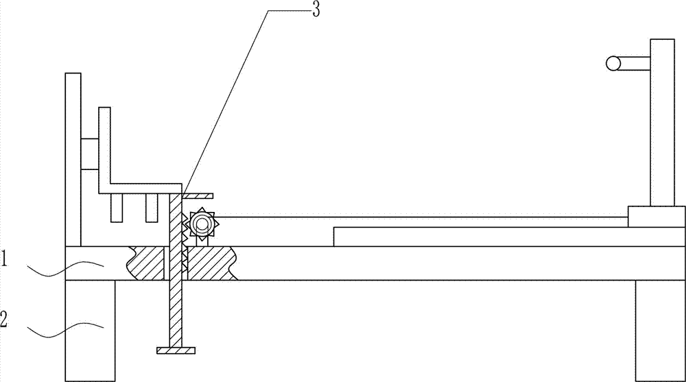
[0031] An eye vision measuring device such as Figure 1-6 As shown, it includes a bottom plate 1 , a leg 2 , a measuring device 3 and a pulling device 4 . Outriggers 2 are respectively provided on the left and right sides of the bottom of the base plate 1 , a measuring device 3 is provided at the left side of the base plate 1 , and a pulling device 4 is provided at the bottom of the base plate 1 .
Embodiment 2
[0033] An eye vision measuring device such as Figure 1-6 As shown, it includes a bottom plate 1 , a leg 2 , a measuring device 3 and a pulling device 4 . Outriggers 2 are respectively provided on the left and right sides of the bottom of the base plate 1 , a measuring device 3 is provided at the left side of the base plate 1 , and a pulling device 4 is provided at the bottom of the base plate 1 .
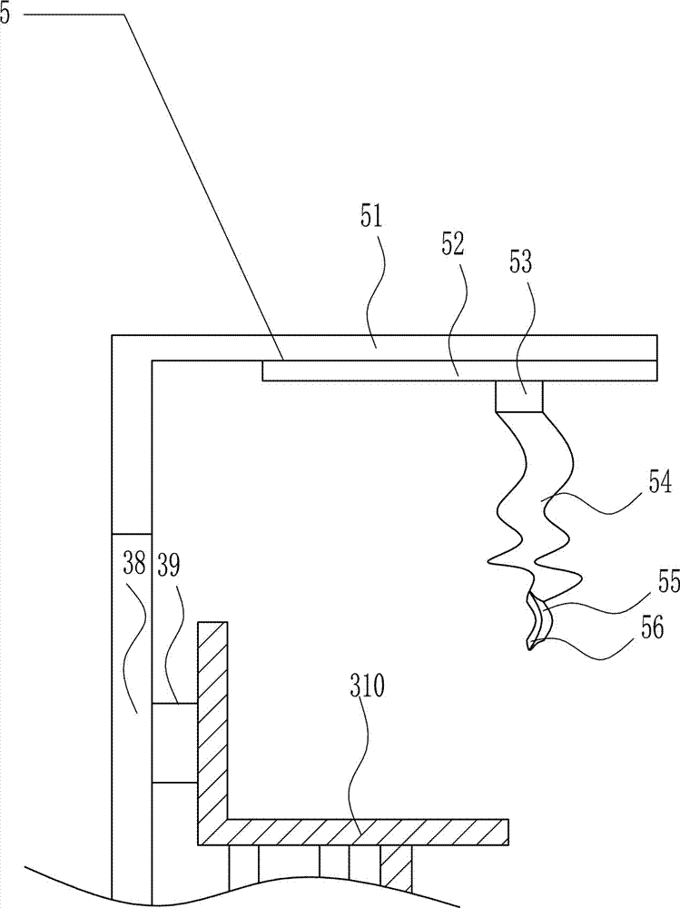
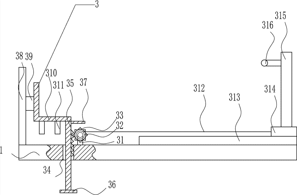
[0034] The measuring device 3 includes a pole 31, a motor 32, a gear 33, a rack 35, a cross plate 36, a pedal 37, a first slide rail 38, a first slide block 39, a seat 310, a support rod 311, and a backguy 312 , the second slide rail 313, the second slide block 314, the eye chart 315 and the lighting lamp 316, the left position of the bottom plate 1 top is provided with a pole 31, the pole 31 is equipped with a motor 32, and the output shaft of the motor 32 is connected to There is a gear 33, a first through hole 34 is opened on the inner side of the left side of the base plate 1,...
Embodiment 3
[0036] An eye vision measuring device such as Figure 1-6 As shown, it includes a bottom plate 1 , a leg 2 , a measuring device 3 and a pulling device 4 . Outriggers 2 are respectively provided on the left and right sides of the bottom of the base plate 1 , a measuring device 3 is provided at the left side of the base plate 1 , and a pulling device 4 is provided at the bottom of the base plate 1 .
[0037]The measuring device 3 includes a pole 31, a motor 32, a gear 33, a rack 35, a cross plate 36, a pedal 37, a first slide rail 38, a first slide block 39, a seat 310, a support rod 311, and a backguy 312 , the second slide rail 313, the second slide block 314, the eye chart 315 and the lighting lamp 316, the left position of the bottom plate 1 top is provided with a pole 31, the pole 31 is equipped with a motor 32, and the output shaft of the motor 32 is connected to There is a gear 33, a first through hole 34 is opened on the inner side of the left side of the base plate 1, ...
PUM
 Abstract
Description
Claims
Application Information