Robot head rotating mechanism

A rotating mechanism and robot technology, which is applied in the field of robots, can solve problems such as high center of gravity, heavy head weight, and limited space, and achieve the effects of alleviating narrow spaces, improving stability, and reducing center of gravity

Pending Publication Date: 2018-01-05
JIANGSU LEIDONG INTELLIGENT MFG CO LTD
View PDF8 Cites 4 Cited by
  • Summary
  • Abstract
  • Description
  • Claims
  • Application Information

AI Technical Summary

Problems solved by technology

[0002] The head movement of an intelligent robot is generally provided with a driving device on the neck to drive the head to rotate, which requires that the driving device must be kept on the same line as the head, which limits the installation position of the driving device and is not conducive to the structural setting of the intelligent robot; , because the output shaft of the driving device is a slender shaft, and the weight of the head is often relatively large, it is easy to make the output shaft of the driving device eccentric during the rotation of the head, thereby shortening the service life of the driving device
[0003] Due to the limited internal space of the robot head, in order to complete multi-degree-of-freedom movements, multiple motors need to be used for driving, which requires a large enough design space reserved inside the robot; and the installation of the motors needs to be considered when placing the motors in the head. , mounting parts and driving devices will inevitably increase the weight of the robot head and affect the stability of the robot head. Therefore, the existing technology has the technical problems of high center of gravity of the head, crowded space and inability to route cables.

Method used


Image

  • Robot head rotating mechanism
  • Robot head rotating mechanism
  • Robot head rotating mechanism

Examples


Embodiment Construction

[0021] The present invention will be further described below in conjunction with the accompanying drawings.

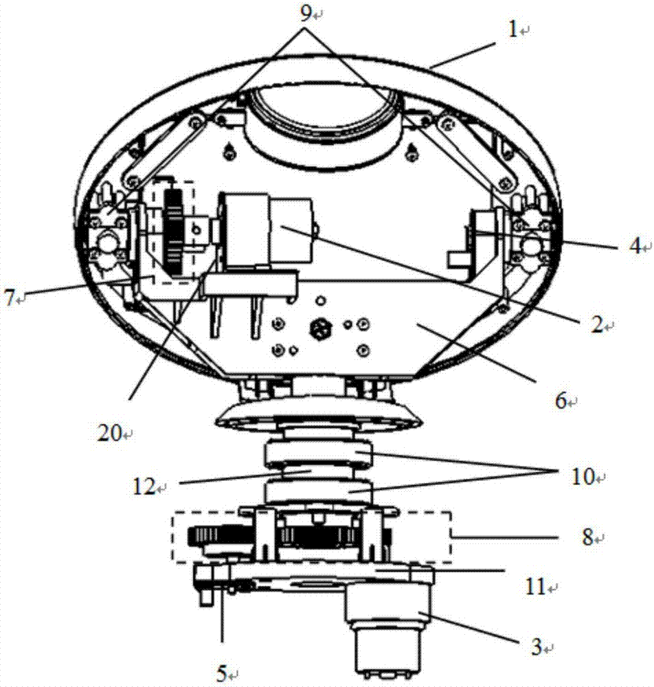
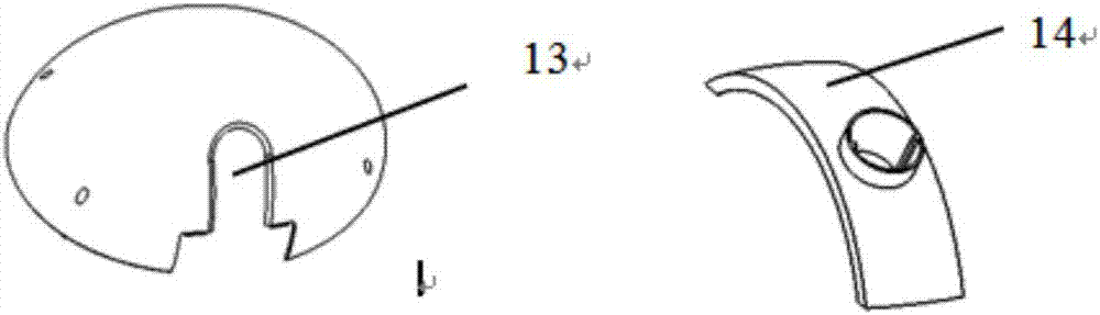
[0022] Such as figure 1 Shown, a kind of robot head rotation mechanism, this head rotation mechanism comprises up and down rotation module, left and right rotation module, head shell 1 and head main bracket 6; The first motor bracket 20, the first transmission mechanism 7, the first angle measurement module 4 and two left and right rotating steel shafts 9 are composed of the left and right rotation modules including the second motor 3, the second motor bracket 11 for fixing the second motor 3, The second transmission mechanism 8, the second angle measurement module 5, the bearing 10 and the neck shaft 12; the head shell 1 further includes a rear skull gap 13 and a gap shielding sheet 14, and the head main bracket 6 passes through two left and right rotating rigid The shaft 9 is connected with the head shell 1, the neck shaft 12 is connected with the head main support ...


PUM


Abstract

The invention provides a robot head rotating mechanism which is characterized in that the robot head rotating mechanism comprises an up-and-down rotating module, a horizontal rotating module, a head shell and a head main support; the up-and-down rotating module is composed of a first motor, a first motor support used for fixing the first motor, a first transmission mechanism, a first angle measurement module, a left rotating steel shaft and a right rotating steel shaft; the horizontal rotating module comprises a second motor, a second motor support used for fixing the second motor, a second transmission mechanism, a second angle measurement module, a bearing and a neck shaft; the head shell further comprises a rear head shell notch and a notch shielding piece, and the head main support isconnected to the head shell through the right and left rotating shafts; the neck shaft is connected to the head main support; and the nodding action of the robot head is controlled by the first motor,and the action of shaking the robot head is controlled by the second motor.

Description

technical field [0001] The invention relates to the field of robots, in particular to a robot head rotation mechanism. Background technique [0002] The head movement of an intelligent robot is generally provided with a driving device on the neck to drive the head to rotate, which requires that the driving device must be kept on the same line as the head, which limits the installation position of the driving device and is not conducive to the structural setting of the intelligent robot; , because the output shaft of the driving device is a slender shaft, and the weight of the head is often relatively large, it is easy to cause the output shaft of the driving device to be eccentric during the rotation of the head, thereby shortening the service life of the driving device. [0003] Due to the limited internal space of the robot head, in order to complete multi-degree-of-freedom movements, multiple motors need to be used for driving, which requires a large enough design space r...

Claims


Application Information

Patent Timeline
Patent Type & Authority Applications(China)
IPC IPC(8): B25J19/00B25J9/12
Inventor 王瑞赵永利李晓伟廖鸿宇
Owner JIANGSU LEIDONG INTELLIGENT MFG CO LTD
Why Eureka
Try Eureka