
Electric power sand throwing fire extinguishing device
A fire extinguishing device and electric power technology, which is applied in fire rescue and other fields, can solve the problems of high danger, high-voltage lines with contacts, danger, etc., and achieve the effects of avoiding electric shock danger, fast driving speed and low cost
- Summary
- Abstract
- Description
- Claims
- Application Information
AI Technical Summary
Problems solved by technology
Method used
Image

Examples
Embodiment
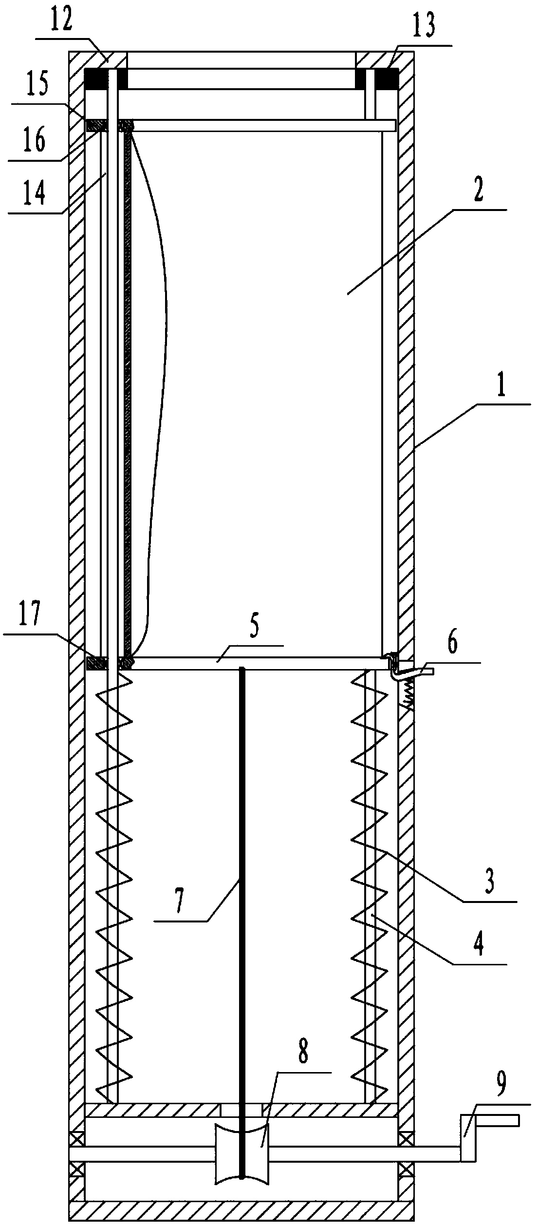
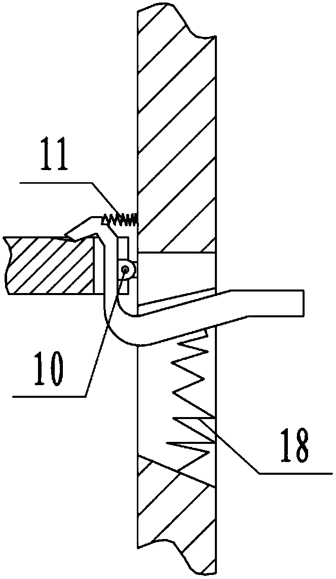
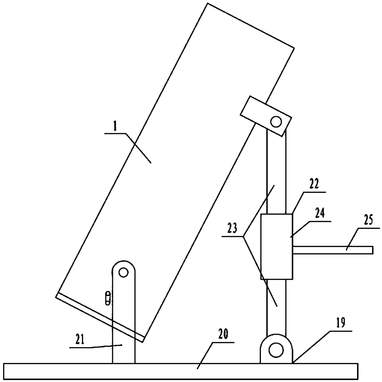
[0022] Example: such as Figure 1-Figure 3 As shown, an electric sand blasting fire extinguishing device includes a launching tube 1 and a sand loading tube 2. The upper end of the sand loading tube 2 is open, placed in the launching tube 1 with the upper opening and can move axially along the launching tube 1, and the bottom passes through the The ejection mechanism is connected to the launch tube 1, and the ejection mechanism includes a spring 3, a guide rod 4 and a push plate 5. The push plate 5 is fixedly connected to the bottom of the launch tube 1, and is socketed on a plurality of guide rods 4 through through holes. The two ends of the rod 4 are fixedly connected in the launch tube 1 and evenly arranged circumferentially along the length direction of the launch tube 1. Each guide rod 4 is sleeved with a spring 3, one end of the spring 3 is fixedly connected to the push plate 5, and the other end Against the launch tube 1, the bottom of the launch tube 1 is provided with...
PUM
 Abstract
Description
Claims
Application Information