Banknote rolling band and banknote rolling mechanism

A banknote winding belt and banknote winding technology is applied in the direction of processing coins or valuable banknotes, coin accepting devices, instruments, etc. The effect of reliability

Inactive Publication Date: 2018-09-28
SHENZHEN YIHUA COMP +2
View PDF6 Cites 0 Cited by
  • Summary
  • Abstract
  • Description
  • Claims
  • Application Information

AI Technical Summary

Problems solved by technology

[0005] In order to solve the above-mentioned problems in the prior art, the present invention provides a banknote rolling belt and a banknote rolling mechanism to solve the problem of inaccurate sensor monitoring caused by the pollution of the banknote rolling belt

Method used


Image

  • Banknote rolling band and banknote rolling mechanism
  • Banknote rolling band and banknote rolling mechanism
  • Banknote rolling band and banknote rolling mechanism

Examples


Embodiment 1

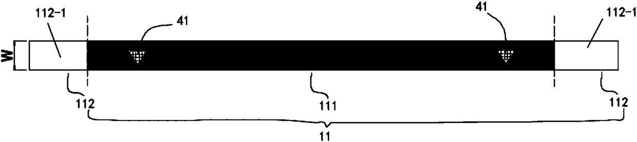
[0029] see figure 1 , as an embodiment of the banknote rolling belt of the present invention, it includes a belt body 11 having a first width W, and the belt body 11 includes a light-shielding first part 111 and a light-shielding degree at both ends of the first part 111 and opposite to the first part 111. The second part 112 of the change. Preferably, the second part 112 includes a light-transmitting part 112 - 1 directly connected to both ends of the first part 111 . In order to enhance the transmittance difference between the first part 111 and the second part 112, to improve the sensitivity of the sensor for monitoring the transmittance of the first part 111 and the second part 112, preferably, the first part 111 is a dark part, and the transmittance of the second part 112 The light part 112-1 is a bright part with high light transmittance. Further, the first part 111 is made of a light-shielding material, such as a black plastic tape, and the second part 112 is made of ...

Embodiment 2

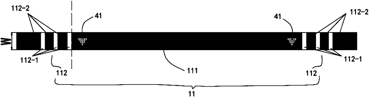
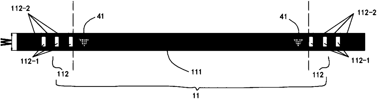
[0038] refer to figure 2 and image 3 , as another embodiment of the banknote rolling belt of the present invention, the difference from Embodiment 1 is that the second part 112 also includes a light-shielding part 112-2, wherein the light-transmitting part 112-1 and the light-shielding part There are multiple portions 112 - 2 , and multiple light transmitting portions 112 - 1 and multiple light shielding portions 112 - 2 are arranged alternately along the length direction of the first portion 111 . It can be understood that this alternate arrangement is arranged at both ends of the first part 111 , which can be symmetrical or asymmetrical. Preferably, the second part 112 at both ends of the first part 111 is arranged symmetrically.

[0039] Wherein, as can be seen from the above, what the first sensor 41 in embodiment 1 monitors is the light and shade change of the belt body 11 once, and in this embodiment, since the second part 112 is composed of the light-transmitting par...

Embodiment 3

[0043] see Figure 4 , as another embodiment of the banknote rolling belt of the present invention, the banknote rolling belt of this embodiment includes a belt body 11 having a first width W and an extension belt 12 protruding along the width direction of the belt body 11, and the extension belt 12 is close to The two ends of belt body 11 are arranged, and this kind of extension can all extend along belt body 11 width direction both sides ( Figure 4 extended on both sides) or only one side. Wherein, the area between the extension belts 12 at the two ends of the belt body 11 is a blank area, and the sensor arranged between the reel and the drum 2 is when the banknote belt does not enter the limit use state, the second sensor 42 monitors the transparent area. The luminosity is always the light transmittance of the blank area between the extension belts 12 at both ends, then when entering the limit use state of the banknote roll belt, the extension belt 12 passes the second se...


PUM


Abstract

The present invention discloses a banknote rolling band, comprising a band body having a first width. The band body comprises a first portion having a certain length of light shielding and second portions located at both ends of the first portion and varying relative to the light shielding degree of the first portion. The invention also discloses a banknote rolling mechanism, comprising a roller rotatable about an axis, a pair of rolling wheels respectively disposed on both sides in the axial direction of the roller and rotatable about respective axes, a pair of banknote rolling bands respectively winding the rolling wheels and the roller and used for tightening or releasing a medium, and a sensor arranged between the rolling wheels and the roller. The sensor is used for monitoring the transmittance of the banknote rolling band passing through the sensor, the banknote rolling band comprises a band body having a first width, the band body comprises a first portion having a certain length of light shielding and second portions located at both ends of the first portion and varying relative to the light shielding degree of the first portion. The banknote rolling band and the banknote rolling mechanism solve the problem that the sensor monitoring is inaccurate after the banknote rolling band is contaminated.

Description

technical field [0001] The invention relates to the field of a banknote rolling device, in particular to a banknote rolling belt and a banknote rolling mechanism. Background technique [0002] Some banknote storage modules are arranged in the ATM machine, common ones are cash boxes, and besides the cash boxes, a temporary storage module, namely a temporary storage module, is also provided. At present, there are two common modes of banknote storage, one is stacking, that is, banknotes are stacked together one by one, and the other is rolling banknotes, that is, using a rolling banknote belt to wind banknotes around a large drum Above, most of the current temporary storage modules use a banknote roll structure, which includes an upper banknote belt, a lower banknote belt, an upper roll wheel, a lower roll wheel, an upper reversing wheel, a lower reversing wheel and a bill drum One end of the upper banknote belt is connected to the upper roll wheel, and the other end is connec...

Claims


Application Information

Patent Timeline
Patent Type & Authority Applications(China)
IPC IPC(8): G07D11/00
CPCB65H2301/41912B65H29/006B65H2701/1912
Inventor 杨登峰
Owner SHENZHEN YIHUA COMP
Why Eureka
Try Eureka