Novel pneumatic hydraulic jack

A pneumatic-hydraulic and pneumatic-hydraulic pump technology, applied in the field of hydraulic jacks, can solve problems such as unstable movements, large space occupation, and easy damage, and achieve the effects of stable lifting, self-fall prevention, and quick reset

Active Publication Date: 2018-11-27
张凯
View PDF7 Cites 2 Cited by
  • Summary
  • Abstract
  • Description
  • Claims
  • Application Information

AI Technical Summary

Problems solved by technology

[0002] There are many kinds of pneumatic hydraulic jacks on the market, but most of them are bulky, laborious to carry, inconvenient to store, and take up a lot of space. The pneumatic hydraulic pump is pressurized through the oil pipe, and there is oil leakage. The hydraulic oil tank and the outside world are also open, and oil leakage will occur due to the tilt measured during use and handling engineering. Most of the pneumatic hydraulic jacks are switch control switches. Easy to damage, unable to achieve stable lifting and falling of the hydraulic cylinder

Method used


Image

  • Novel pneumatic hydraulic jack
  • Novel pneumatic hydraulic jack
  • Novel pneumatic hydraulic jack

Examples


Embodiment Construction

[0023] The following will clearly and completely describe the technical solutions in the embodiments of the present invention with reference to the accompanying drawings in the embodiments of the present invention. Obviously, the described embodiments are only some, not all, embodiments of the present invention. Based on the embodiments of the present invention, all other embodiments obtained by persons of ordinary skill in the art without making creative efforts belong to the protection scope of the present invention.

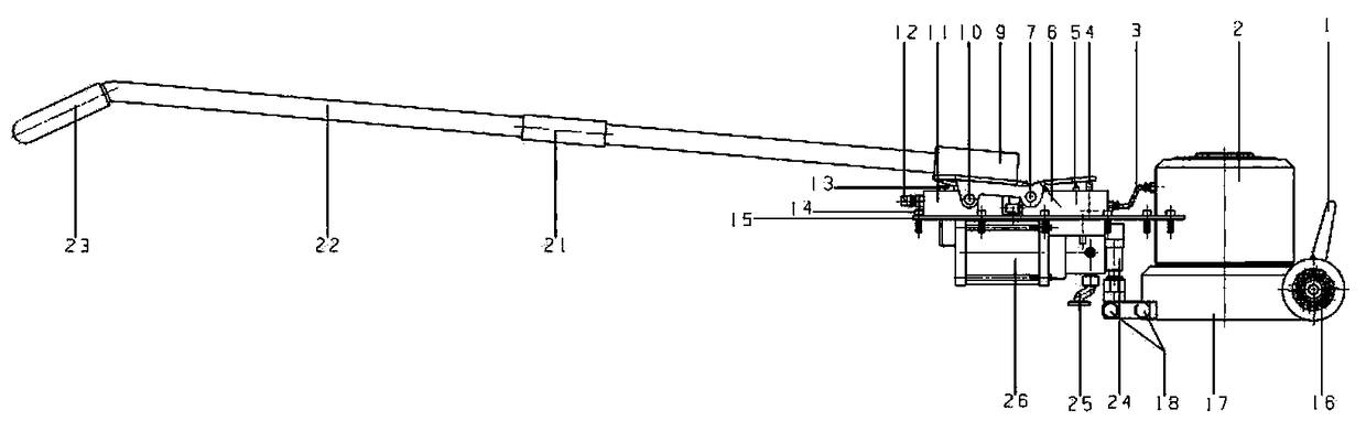
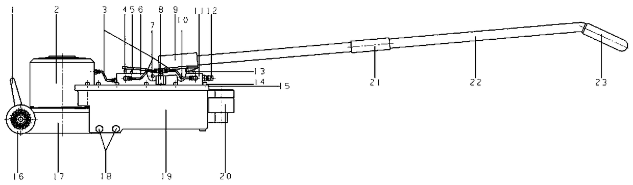
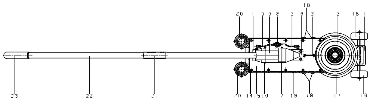
[0024] The embodiment of the invention discloses a new type of pneumatic hydraulic jack which is manually controlled to adjust the lifting height, has a compact structure, does not leak hydraulic oil when tilted sideways, and saves storage space.

[0025] Please refer to the attached Figure 1-3 , is a novel pneumatic hydraulic jack disclosed by the present invention, the assembly structure is:

[0026] The hydraulic oil tank 19 is connected to the pneumatic ...


PUM


Abstract

The invention discloses a novel pneumatic hydraulic jack, which mainly comprises a control handle, a lifting control connecting plate, an air intake control valve seat, a falling control valve seat, ahydraulic oil tank vent valve, a pneumatic hydraulic pump assembly, a hydraulic cylinder, a hydraulic oil tank, a base, a support seat and a moving wheel. Wherein the hydraulic oil tank is connectedwith and fixed to the intake control valve seat through a pneumatic hydraulic pump assembly, Hydraulic tank vent valve, Retreat control valve seat, the oil tank ventilation valve seat, the air intakecontrol valve seat, the drop control valve seat and the hydraulic cylinder are communicated with each other through a pipeline, the hydraulic cylinder and the hydraulic oil tank are connected with each other through a high-pressure pipeline, the lift control connecting plate is fixed above the air intake control valve seat and the drop control valve seat, and the control handle is installed on thelift control connecting plate; An independent intake control valve seat is provided for supplying a pneumatic hydraulic pump assembly as a power source, and an independent drop control valve seat isprovided, which is provided with a slow-speed and a fast-speed two-stage reset needle valve, so as to realize uniform speed descent.

Description

technical field [0001] The invention relates to the field of hydraulic jacks, in particular to a novel pneumatic hydraulic jack. Background technique [0002] There are many kinds of pneumatic hydraulic jacks on the market, but most of them are bulky, laborious to carry, inconvenient to store, and take up a lot of space. The pneumatic hydraulic pump is pressurized through the oil pipe, and there is oil leakage. The hydraulic oil tank and the outside world are also open, and oil leakage will occur due to the tilt measured during use and handling engineering. Most of the pneumatic hydraulic jacks are switch control switches. It is easy to be damaged, and the stable lifting and falling of the hydraulic cylinder cannot be achieved. [0003] Therefore, it is an urgent problem for those skilled in the art to propose a new type of pneumatic hydraulic jack that uses the principle of leverage to control the lifting control valve and the two-stage needle valve that controls the spe...

Claims


Application Information

Patent Timeline
Patent Type & Authority Applications(China)
IPC IPC(8): B66F3/42B66F3/25
CPCB66F3/25B66F3/42
Inventor 张凯
Owner 张凯
Why Eureka
Try Eureka