Regenerator and Pulse Tube Refrigerator Using the Regenerator Structure

A technology for pulse tube refrigerators and regenerators, which is applied in the structure of pulse tube refrigerators and the field of pulse tube refrigerators. Uniformity, reducing the effect of uneven flow

Active Publication Date: 2020-06-02
TONGJI UNIV
View PDF6 Cites 0 Cited by
  • Summary
  • Abstract
  • Description
  • Claims
  • Application Information

AI Technical Summary

Problems solved by technology

Also due to the structural defects of the regenerator, the refrigeration power of the pulse tube refrigerator is limited to the kilowatt level.

Method used


Image

  • Regenerator and Pulse Tube Refrigerator Using the Regenerator Structure
  • Regenerator and Pulse Tube Refrigerator Using the Regenerator Structure
  • Regenerator and Pulse Tube Refrigerator Using the Regenerator Structure

Examples


Embodiment 1

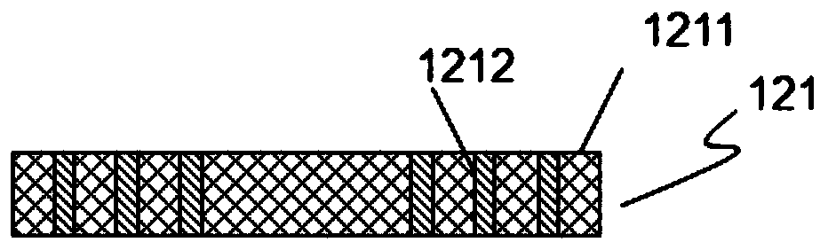
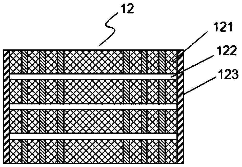
[0029] A regenerator, refer to figure 1 , figure 2 As shown, it consists of a regenerator tube 123 and a plurality of spaced regenerator packing units 121 packed in the regenerator tube 123, and there is a gap 122 between two adjacent regenerator packing units 121, and the regenerator Heater filler unit 121 is composed of filler 1211 and separators 1212 , separators 1212 are arranged at intervals, fillers 1211 are filled between adjacent separators 1212 , fillers 1211 are arranged between separators 1212 and regenerator tubes 123 . The regenerator filling units 121 are arranged at intervals along the length direction of the regenerator tube 123 , and the fillers 1211 are distributed at intervals along the radial direction of the regenerator tube 123 .

[0030] The partition can be constructed in two ways:

[0031] The first structure is: the partition 1212 is a plurality of annular plates or annular tubes of different diameters coaxially sleeved, the filler 1211 is filled b...

Embodiment 2

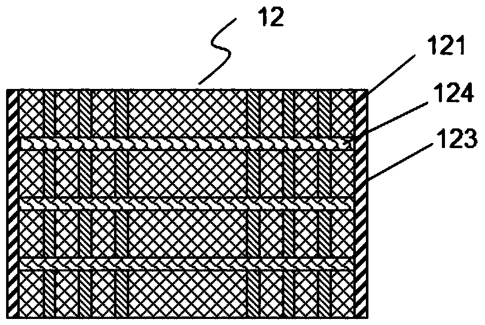
[0036] A regenerator, refer to figure 1 , image 3 , consisting of a regenerator tube 123 and a plurality of regenerator packing units 121 arranged at intervals filled in the regenerator tube 123, a porous material 124 is arranged between two adjacent regenerator packing units 121, and the regenerator The filler unit 121 is composed of fillers 1211 and separators 1212 , the separators 1212 are arranged at intervals, the fillers 1211 are filled between adjacent separators 1212 , and the fillers 1211 are arranged between the separators 1212 and the regenerator tubes 123 . The regenerator filling units 121 are arranged at intervals along the length direction of the regenerator tube 123 , and the fillers 1211 are distributed at intervals along the radial direction of the regenerator tube 123 .

[0037] The partition can be constructed in two ways:

[0038] The first structure is: the partition 1212 is a plurality of annular plates or annular tubes of different diameters coaxiall...

Embodiment 3

[0043] A regenerator, refer to Figure 4 , Figure 5 As shown, in this embodiment, the regenerator is a hollow structure. Specifically, the regenerator in this embodiment is composed of a regenerator tube 123 and a plurality of spaced regenerator filling units 121 filled in the regenerator tube 123, and two adjacent regenerator filling units 121 There is a gap 122 between them, and the regenerator packing unit 121 is composed of a filler 1211 and a separator 1212. There are fillers 1211 in between. The regenerator filling units 121 are arranged at intervals along the length direction of the regenerator tube 123 , and the fillers 1211 are distributed at intervals along the radial direction of the regenerator tube 123 .

[0044] In this embodiment, the regenerator filling unit 121 is provided with a hollow portion for placing the vessel 14 , and the regenerator filling unit 121 is sheathed outside the vessel 14 .

[0045] The partition can be constructed in two ways:

[004...


PUM


Abstract

The invention relates to a novel regenerator and a pulse pipe refrigerator adopting the regenerator structure. The novel regenerator consists of a regenerator pipe, and multiple regenerator filler units arranged in the regenerator pipe at intervals; gaps or porous materials are formed between two adjacent regenerator filler units; the regenerator filler units consist of fillers and separation plates; the separation plates are arranged at intervals; the fillers are filled between the adjacent separation plates; and the fillers are arranged between the separation plates and the regenerator pipe.The invention further provides the pulse pipe refrigerator adopting the regenerator structure. Compared with the prior art, the regenerator reduces nonuniform flowing of gas in each unit and in the whole regenerator, and reduces the problem of low efficiency of the regenerator caused by nonuniform gas currents.

Description

technical field [0001] The invention belongs to the refrigeration field and relates to a pulse tube refrigerator structure, in particular to a regenerator and a pulse tube refrigerator adopting the regenerator structure. Background technique [0002] The regenerator is the core component of the pulse tube refrigerator. The longer the regenerator, the greater the resistance. Therefore, in order to avoid the excessive resistance of the regenerator, the length of the regenerator is generally designed to be about 50mm in the industry. , in actual use, the diameter of the regenerator should be increased according to the cooling power. But as the cooling power increases, the aspect ratio of the regenerator becomes smaller, and the regenerator becomes dish-shaped. At this time, another problem faced by the regenerator is the uniformity of the air flow. Therefore, the resistance of the regenerator and the uniformity of the air flow become the main contradiction in the design proces...

Claims


Application Information

Patent Timeline
Patent Type & Authority Patents(China)
IPC IPC(8): F25B40/06F25B9/14
CPCF25B9/145F25B40/06F25B2309/1412
Inventor 朱绍伟
Owner TONGJI UNIV
Why Eureka
Try Eureka