Injection mold

A technology for injection molds and mold cores, applied in the field of injection molds, can solve problems such as insufficient exhaust, low efficiency, trapped air, etc., and achieve the effects of eliminating trapped air, improving product quality, and increasing speed

Inactive Publication Date: 2019-04-02
AAC TAIRUIMEI MODULE SHENZHEN CO LTD
View PDF6 Cites 3 Cited by
  • Summary
  • Abstract
  • Description
  • Claims
  • Application Information

AI Technical Summary

Problems solved by technology

[0002] Existing industrial products usually adopt the injection molding process, and the most important thing in the injection molding process is the structure of the mold. In the production process of industrial products, when the mold is closed and injected with hot-melt plastic, air is often brought in, and the hot-melt When the shaped plastic flows in the cavity

Method used


Image

  • Injection mold
  • Injection mold
  • Injection mold

Examples


Embodiment

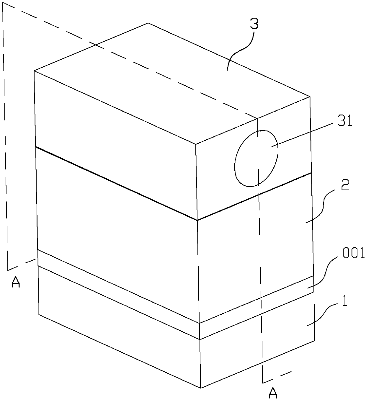
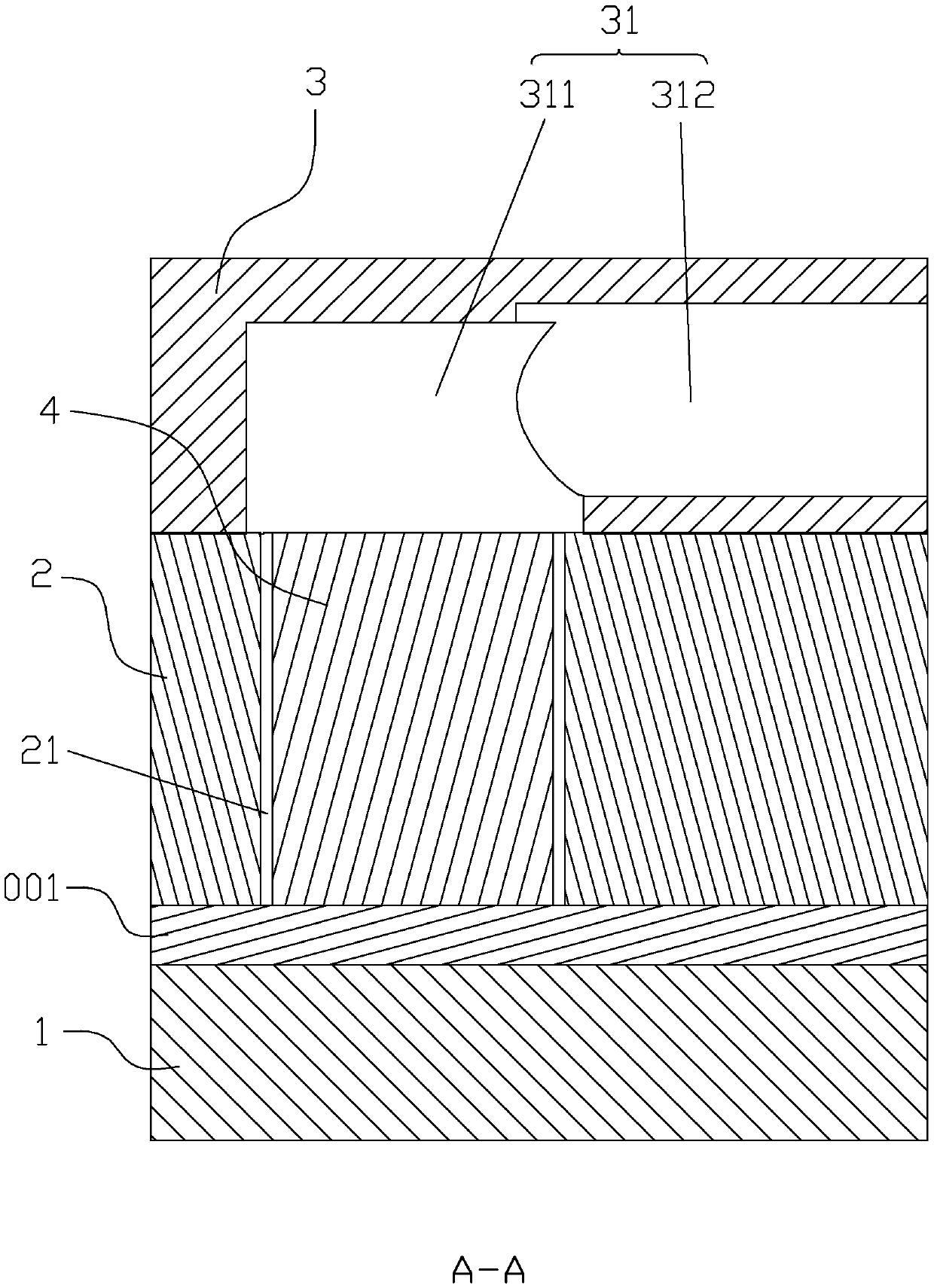
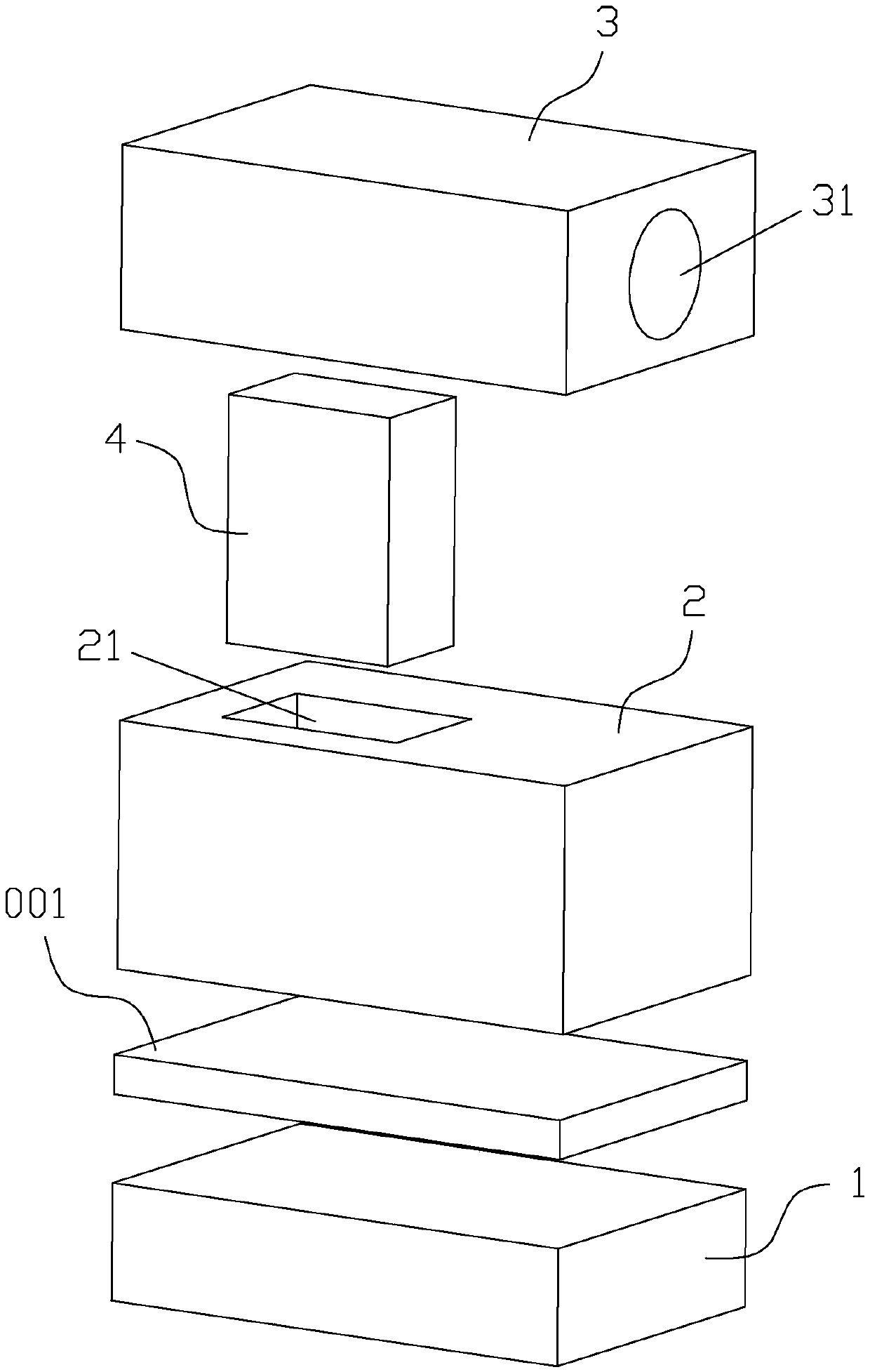
[0017] In this example, if Figure 1-3 As shown, the injection mold includes: a first mold core 1, a second mold core 2, a third mold core 3, an insert 4 and an exhaust device (not shown), the first mold core 1, the second mold core 2 and The third mold core 3 is arranged in sequence, the second mold core 2 is provided with an inlay channel 21, the third mold core 3 is provided with an exhaust channel 31, and the exhaust channel 31 and the inlay channel 21 are correspondingly arranged, and the exhaust channel 31 is connected to the exhaust channel 21. The air device is connected, the insert 4 is embedded in the inlay channel 21, and there is a gap for air to pass between the insert 4 and the inner wall of the inlay channel 21, when the first mold core 1, the second mold core 2 and the third mold core 3. During injection mold clamping, a cavity is formed between the first mold core 1 and the second mold core 2, the inlay channel 21 communicates with the cavity and the exhaust c...


PUM


Abstract

The invention provides an injection mold comprising a first mold core, a second mold core, a third mold core, a mold insert and an exhaust device. The second mold core is provided with an inlaying channel, and the third mold core is provided with an exhaust channel arranged correspondingly to the inlaying channel; the exhaust channel is connected with the exhaust device, and the mold insert is inlaid in the inlaying channel; spacing for air to pass is formed between the inner walls of the mold insert and the inlaying channel; when the first mold core, the second mold core and the third mold core are combined through injection molding, a cavity is formed between the first mold core and the second mold core, and the inlaying channel communicates with the cavity and the exhaust channel; molten plastic in the cavity is prevented from entering the exhaust channel by the mold insert, and the exhaust device is used for vacuum-pumping the exhaust channel so that air in the cavity is pumped out. According to the injection mold, the rate of air discharge of the injection mold can be improved, and the air trapping phenomenon of the injection mold can be eliminated effectively, so that the quality of products produced with the injection mold is improved.

Description

technical field [0001] The invention belongs to the technical field of injection molds, in particular to an injection mold. Background technique [0002] Existing industrial products usually adopt the injection molding process, and the most important thing in the injection molding process is the structure of the mold. In the production process of industrial products, when the mold is closed and injected with hot-melt plastic, air is often brought in, and the hot-melt When the shaped plastic flows in the cavity of the mold, the air will be squeezed. If the air cannot be effectively discharged, it will cause air trapping. Although the air gap is used to exhaust in the prior art, this exhaust The efficiency of the method is not high, and the exhaust is not timely enough when producing products with a faster cooling rate, which will affect the quality of injection molding products. Contents of the invention [0003] The technical problem to be solved by the present invention ...

Claims


Application Information

Patent Timeline
IPC IPC(8): B29C45/34
CPCB29C45/34
Inventor 冯炉邵状
Owner AAC TAIRUIMEI MODULE SHENZHEN CO LTD
Why Eureka
Try Eureka