Inflating device with air storage tube

A gas storage tank and gas storage technology, which can be used in the direction of pump devices, liquid displacement machinery, variable displacement pump components, etc., and can solve problems such as inconvenient use

Active Publication Date: 2019-05-28
BETO ENG & MARKETING
View PDF8 Cites 0 Cited by
  • Summary
  • Abstract
  • Description
  • Claims
  • Application Information

AI Technical Summary

Problems solved by technology

[0003] In order to allow the pumping device to output gases with different pressure values ​​according to the needs of use, the applicant once proposed an invention patent No. I495788, Taiwan, China. Although this invention patent can output low-pressure gas and hi...

Method used


Image

  • Inflating device with air storage tube
  • Inflating device with air storage tube
  • Inflating device with air storage tube

Examples


Embodiment Construction

[0032] Before the present invention is described in detail, it should be noted that in the following description, similar elements are denoted by the same numerals.

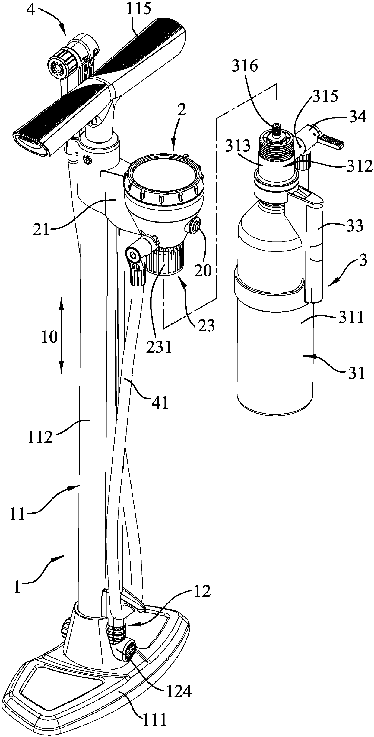
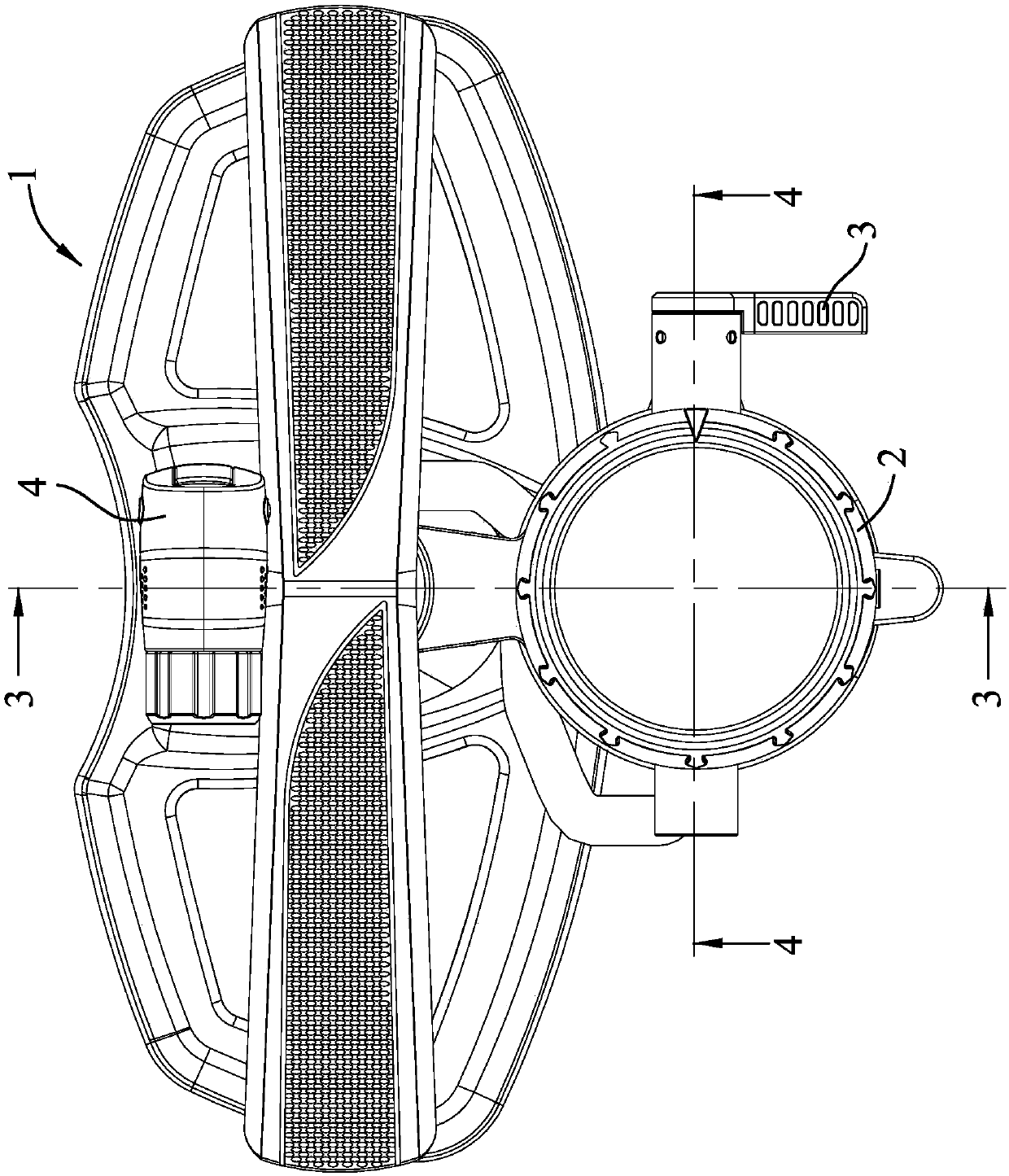
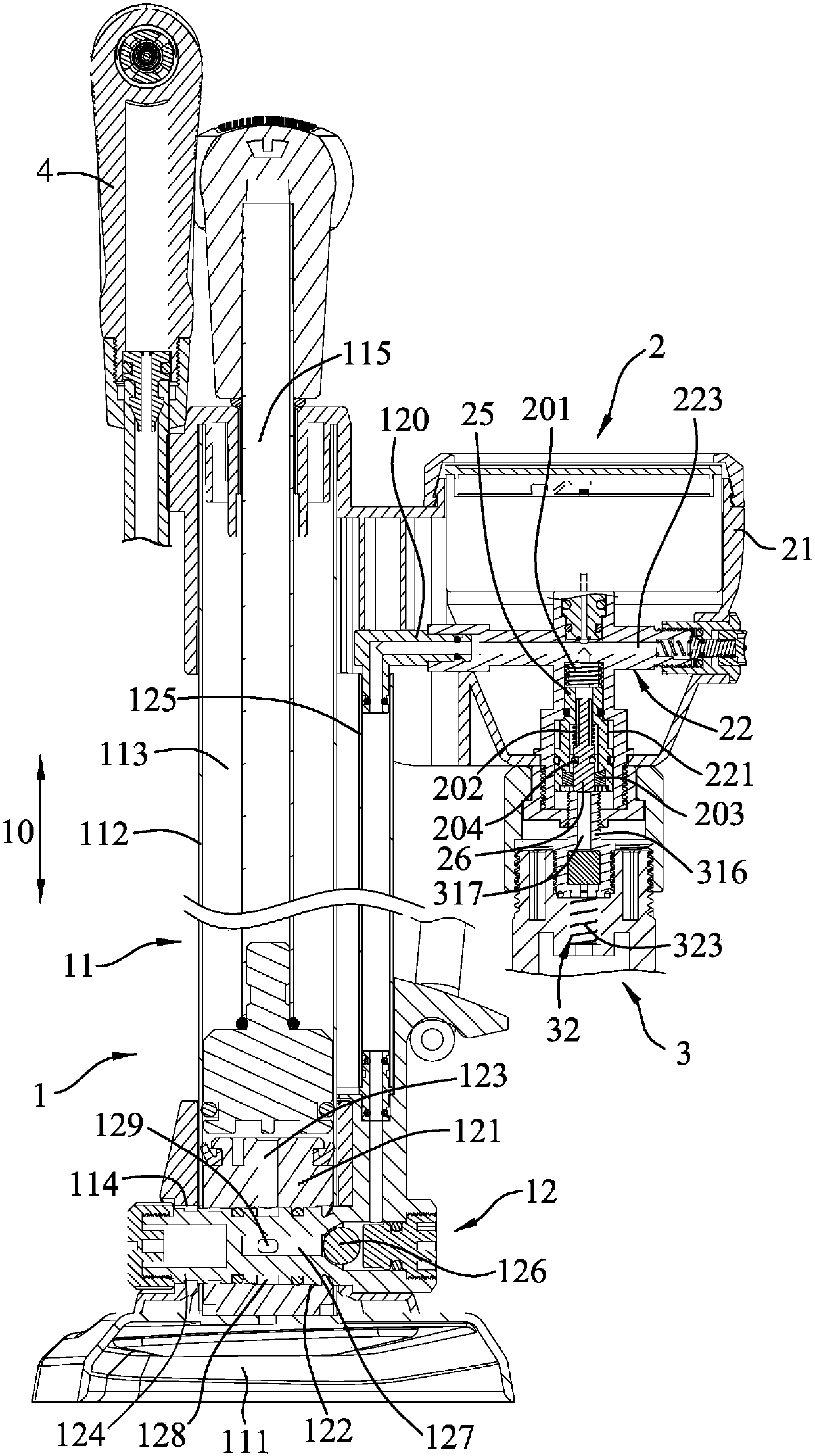
[0033] refer to Figure 1 to Figure 4 , a first embodiment of the inflating device of the present invention can output low-pressure gas and high-pressure gas according to the needs of use. The low-pressure gas and the high-pressure gas are only relative values, that is to say, the pressure values ​​of the aforementioned gases are not particularly limited. , the inflating device comprises a gas generating mechanism 1, a split flow control mechanism 2 installed on the gas generating mechanism 1 and controlling the gas flow direction, and an air storage tank 3 detachably installed under the split flow control mechanism 2, And an inflating unit 4 installed on the split flow control mechanism 2, the air storage tank 3 can output high-pressure gas, and the inflating unit 4 can output low-pressure gas with a relatively ...


PUM


Abstract

The invention discloses an inflating device with an air storage tube. The device comprises an air generating mechanism, a flow dividing air controlling mechanism which is installed on the air generating mechanism, an inflating unit and an air storage tube body, wherein the flow dividing air controlling mechanism is provided with a flow dividing seat which is connected with the air generating mechanism and the inflating unit and an air controlling unit which is installed on the flow dividing seat and can be switched between an air storage position and an inflating position, and the air storagetube is detachably installed on the flow dividing seat. According to the inflating device, air can be guided to flow to the inflating unit or the air storage tube by the cooperation of the above structures, and the air storage tube can be separated from other components because the air storage tube is detachably installed on the flow dividing seat to achieve the purpose of separate using.

Description

technical field [0001] The invention relates to an inflating device, in particular to an inflating device with an air storage cylinder which can provide high-pressure gas and low-pressure gas. Background technique [0002] Existing manual pumping devices can roughly be divided into direct air supply type and air storage air supply type according to different air supply methods. The direct air supply type operates a piston assembly by manpower and sucks air into a cylinder. The gas is directly pumped into an object to be inflated through an inflating unit. This gas supply method is suitable for filling items such as balloons, low-pressure tires, etc. because the output gas pressure value is low. The gas storage and supply type is to store the gas in a gas storage tank in advance, and then the gas storage tank will press the high-pressure gas to the inside of the object to be inflated. Since the two gas supply methods and structures are different, users need to buy two Inflat...

Claims


Application Information

Patent Timeline
IPC IPC(8): F04B33/00F04B41/02F04B39/10
Inventor 王罗平
Owner BETO ENG & MARKETING
Why Eureka
Try Eureka