Pay-off device for power construction

A pay-off device and electric power construction technology, which is applied in the directions of transportation and packaging, delivery of filamentous materials, thin material processing, etc., can solve the problem that the cable pay-off device cannot be crossed, etc., and achieves remarkable applicability and smooth pay-off process Effect

Inactive Publication Date: 2019-08-30
STATE GRID HENAN ELECTRIC ZHOUKOU POWER SUPPLY +1
View PDF6 Cites 1 Cited by
  • Summary
  • Abstract
  • Description
  • Claims
  • Application Information

AI Technical Summary

Problems solved by technology

However, the cable pay-off device of the present invention cannot cross higher steps, that is, it is not suitable for use in places with many potholes.

Method used


Image

  • Pay-off device for power construction
  • Pay-off device for power construction
  • Pay-off device for power construction

Examples


Embodiment 1

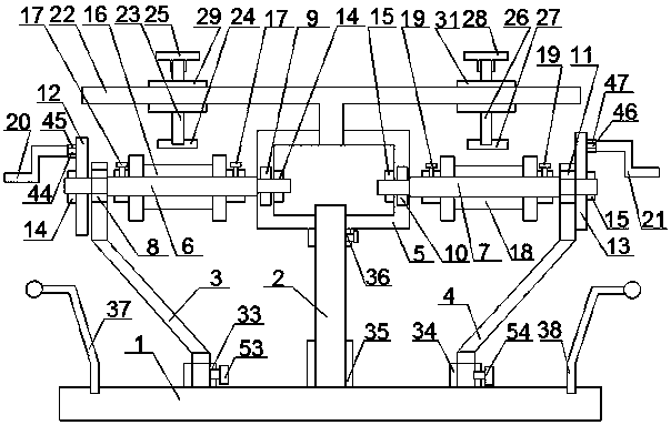
[0037] Such as figure 1 As shown, a wire-releasing device for electric power construction includes a base 1 and a wire-releasing module arranged on the base;

[0038]The pay-off module includes a connecting shaft 2 arranged on the base 1, a first support rod 3 arranged on the base 1 and on the left side of the connecting shaft 2, a second support rod 3 arranged on the base 1 and on the right side of the connecting shaft 2 Support rod 4, the shaft sleeve 5 that is arranged on the upper end of the connecting shaft 2, the first shaft rod 6 that is arranged between the left side of the shaft sleeve 5 and the upper end of the first support rod 3, is arranged on the right side of the shaft sleeve 5 and the second The second shaft 7 between the upper ends of the support rods 4, the first bearing 8 arranged at the connection between the left end of the first shaft 6 and the first support rod 3, and the first bearing 8 arranged at the right end of the first shaft 6 and connected with t...

Embodiment 2

[0069] Such as Image 6 As shown, the difference between the present embodiment and the first embodiment is that a transmission unit is further provided between the right end of the first shaft 6 and the left end of the second shaft 7 .

[0070] The transmission unit includes a transmission card 48 arranged between the right end of the first shaft 6 and the left end of the second shaft 7 , and a first fixed part arranged at the connection between the left end of the transmission card 48 and the first shaft 6 . The bolt 49 and the first fixing nut 50 , the second fixing bolt 51 and the second fixing nut 52 arranged at the joint between the right end of the transmission card 48 and the second shaft 7 .

[0071] The left end of the transmission card 48 is clamped with the right end of the first shaft 6, and the connection between the transmission card 48 and the first shaft 6 is fixed by the first fixing bolt 49 and the first fixing nut 50. The transmission card 48 The right end...

Embodiment 3

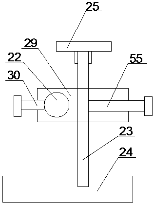
[0077] Such as Figure 7 , 8 As shown in . The position is fixed by the sixth limit bolt 57, and the length of the first limit plate 24 is equal to the width of the wire clamping groove of the first wire barrel 16;

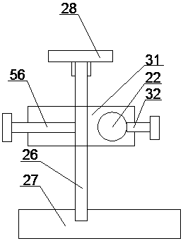
[0078] The second limit column 26 is directly connected to the right end of the limit rod 22, and the connection between the second limit column 26 and the limit rod 22 is fixed by the seventh limit bolt 58. The second limit plate 27 The length is equal to the width of the clamping groove of the second wire cylinder 18.

[0079] When it is necessary to fix the unclamped cables, only the sixth limit bolt 57 and the seventh limit bolt 58 are loosened first, and the first limit column needs to be screwed down by means of the first handle 25 and the second handle 28 23. The second limit post 26, so that the first limit pressure plate 24 or the second limit pressure plate 27 can press the entire upper surface of the first line barrel 16 and the second line barrel 18...


PUM


Abstract

The invention provides a pay-off device for power construction. The device comprises a base, and a pay-off module. The pay-off module comprises a connecting shaft, a first supporting rod, a second supporting rod, a shaft sleeve arranged on the upper end of the connecting shaft, a first shaft rod arranged between the shaft sleeve and the first supporting rod, a second shaft rod arranged between theshaft sleeve and the second supporting rod, a first bearing arranged at the connecting position of the first shaft rod and the first supporting rod, a second bearing arranged at the connecting position of the first shaft rod and the shaft sleeve, a third bearing arranged at the connecting position of the left end of the second shaft rod and the shaft sleeve, a fourth bearing arranged at the connecting position of the right end of the second shaft rod and the second supporting rod, a limiting unit and a transmission unit, wherein the connecting shaft, the first supporting rod and the second supporting rod are arranged on the base, and the limiting unit and the transmission unit are arranged on the shaft sleeve. Pay-off is conveniently and efficiently carried out, detaching, and assemblingcan be carried out, and carrying and transport are facilitated.

Description

technical field [0001] The invention relates to the field of electric power construction equipment, in particular to a wire-releasing device for electric power construction. Background technique [0002] In order to facilitate transportation, the cables are usually fixed in a disc type, and in the process of use, in order to improve the efficiency of the wires, it is usually necessary to use a tool such as a wire rack. [0003] Common pay-off racks include flat pay-off racks, folding pay-off racks, hydraulic pay-off racks, trapezoidal pay-off racks, bolt pay-off racks, etc. Although the above-mentioned pay-off racks have various advantages, they are There are also shortcomings such as high cost price, poor portability, and insufficient convenience during use. [0004] The invention with the publication number CN 105600581 A discloses a cable pay-off device, including a support rod, a support plate, a shelving rod, a positioning piece and a movable seat, and the movable seat...

Claims


Application Information

Patent Timeline
Patent Type & Authority Applications(China)
IPC IPC(8): B65H49/32B65H49/34B65H49/38B65H49/36B65H59/04
CPCB65H49/324B65H49/34B65H49/36B65H49/38B65H59/04B65H2701/34
Inventor 乔立华耿进锋孙建华史红伟李红英韦光辉崔大田秦跃杰娄高峰范璞玉
Owner STATE GRID HENAN ELECTRIC ZHOUKOU POWER SUPPLY
Why Eureka
Try Eureka