Positioning and locking mechanism of small-diameter steel pipe rotating hanger

A positioning and locking, small-caliber technology, applied in manufacturing tools, workpiece clamping devices, etc., can solve the problems of inconvenient disassembly of positioning pins, impact on the work efficiency of staff, and impact on the service life of the locking mechanism, and prolong the service life of the equipment. , avoid direct rigid connection, improve the effect of service life

Active Publication Date: 2020-11-24
德清金瑞机械设备有限公司
View PDF5 Cites 0 Cited by
  • Summary
  • Abstract
  • Description
  • Claims
  • Application Information

AI Technical Summary

Problems solved by technology

[0002] In the actual manufacturing process, it is necessary to fix the locking parts through the bolts. During the working process of the equipment, there will be certain vibrations, and there will be certain errors during the vibrations. If these errors cannot be eliminated, there will be Affect the service life of the locking mechanism; the locking mechanism will carry a certain pressure when locking. In order to ensure the normal operation of the equipment, it is necessary to regularly maintain and replace the locking parts of the locking mechanism, but the general positioning pin It is inconvenient to disassemble, which has a certain impact on the work efficiency of the staff

Method used


Image

  • Positioning and locking mechanism of small-diameter steel pipe rotating hanger
  • Positioning and locking mechanism of small-diameter steel pipe rotating hanger
  • Positioning and locking mechanism of small-diameter steel pipe rotating hanger

Examples


Embodiment Construction

[0021] The technical solutions in the embodiments of the present invention will be clearly and completely described below in conjunction with the accompanying drawings in the embodiments of the present invention. Obviously, the described embodiments are only a part of the embodiments of the present invention, rather than all the embodiments. Based on the embodiments of the present invention, all other embodiments obtained by those of ordinary skill in the art without creative work shall fall within the protection scope of the present invention.

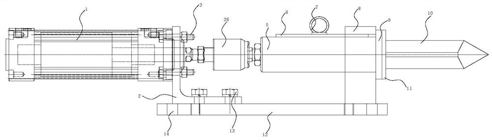
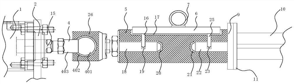
[0022] See Figure 1-3 , The present invention provides a technical solution: a small-diameter steel pipe rotary hanger positioning and locking mechanism includes a floating connection mechanism 4, a guide seat 5 and a bottom plate 12. The bottom plate 12 is longitudinally penetrated with positioning holes 14, the number of 14 is at least four , An L-shaped positioning plate 2 is installed on the top of the bottom plate 12, and a connect...


PUM


Abstract

The invention discloses a positioning and locking mechanism for a small-caliber steel pipe rotating hanger, and relates to the technical field of mechanical production. The positioning and locking mechanism for the small-caliber steel pipe rotating hanger comprises a floating connecting mechanism, a guide seat and a bottom plate, wherein the bottom plate is longitudinally provided with a positioning hole in a penetrating mode, the top of the bottom plate is provided with an L-shaped positioning plate, the L-shaped positioning plate is in threaded connection with fixing bolts, one side of the L-shaped positioning plate is provided with an air cylinder, the fixing bolts penetrate through the L-shaped positioning plate to fix the air cylinder on the outer wall of one side of the L-shaped positioning plate, a piston rod is arranged on the air cylinder, the piston rod transversely penetrates through the L-shaped positioning plate and extends to the other side of the L-shaped positioning plate, a free end of the piston rod is connected with a connecting seat through the floating connecting mechanism, a first connecting rod is connected to the side, far away from the air cylinder, of theconnecting seat, and the guiding seat is arranged on the side, far away from the air cylinder, of the connecting seat. According to the positioning and locking mechanism, the locking effect is good, the maintenance is convenient, and the working efficiency of workers is improved.

Description

Technical field [0001] The invention relates to the technical field of mechanical production, in particular to a positioning and locking mechanism for a small-diameter steel pipe rotary hanger. Background technique [0002] In the actual manufacturing process, the locking parts need to be fixed by bolts. During the operation of the equipment, a certain amount of vibration will occur, and certain errors will occur during vibration. If these errors cannot be eliminated, they will Affect the service life of the locking mechanism; the locking mechanism will carry a certain pressure when it is locked. In order to ensure the normal operation of the equipment, it is necessary to regularly maintain and replace the locking parts of the locking mechanism, but the general positioning pin The disassembly is inconvenient, which has a certain impact on the work efficiency of the staff. Summary of the invention [0003] The purpose of the present invention is to provide a positioning and lockin...

Claims


Application Information

Patent Timeline
Patent Type & Authority Patents(China)
IPC IPC(8): B25B11/00
CPCB25B11/00
Inventor 金跃强
Owner 德清金瑞机械设备有限公司
Why Eureka
Try Eureka