Chemical material finished product dehydration tank

A technology for dehydrating tanks and materials, which is applied in dehydration/drying/concentrated sludge treatment, chemical instruments and methods, and separation of dispersed particles. It can solve problems such as uneven heating of materials, poor hot air circulation, and inconsistent dehydration degrees, and achieve dehydration uniform effect

Pending Publication Date: 2019-12-20
徐春霞
View PDF4 Cites 2 Cited by
  • Summary
  • Abstract
  • Description
  • Claims
  • Application Information

AI Technical Summary

Problems solved by technology

[0003] When testing the sludge, it is necessary to dehydrate the sludge. However, when the existing dehydration tank is performing dehydration, the hot air is simply input into the dehydration tank. When the material is dense, the internal hot air circulation is relatively slow. Poor, the materials in different positions are heated unevenly, and the other positions are not consistent with the degree of dehydration, resulting in uneven dehydration of the materials inside the dehydration tank, and the air after drying in the existing dehydration tanks is usually directly discharged without any treatment The moisture and dust contained in the hot air will have a certain impact on the surrounding environment. For this, a chemical material product dehydration tank is necessary.

Method used


Image

  • Chemical material finished product dehydration tank
  • Chemical material finished product dehydration tank
  • Chemical material finished product dehydration tank

Examples


Embodiment Construction

[0025] In order to make the technical means, creative features, goals and effects achieved by the present invention easy to understand, the present invention will be further described below in conjunction with specific embodiments.

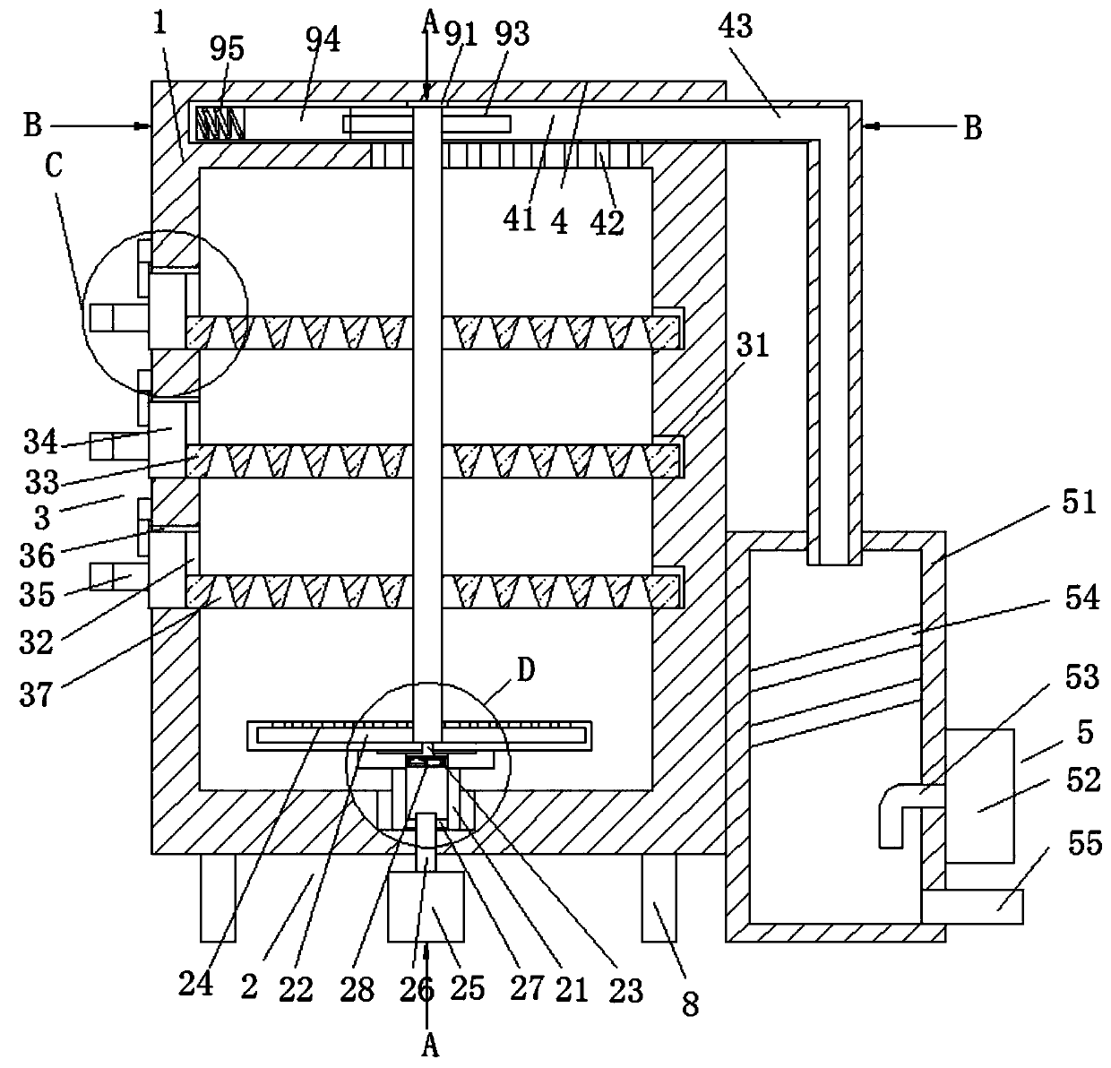
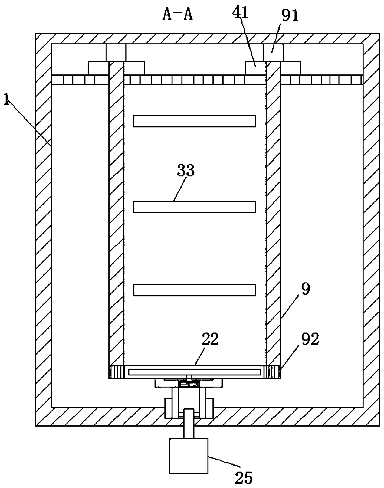
[0026] like Figure 1-Figure 7 As shown, a chemical material product dehydration tank according to the present invention includes a hollow tank body 1, a heating mechanism 2 is fixedly installed at the bottom of the tank body 1, and the tank body located above the heating mechanism 2 1 is provided with three placement mechanisms 3 evenly and equidistantly, and an air outlet mechanism 4 is arranged on the top inner wall of the tank body 1, one end of the air outlet mechanism 4 penetrates the corresponding side wall of the tank body 1 and extends to the outside of the tank body 1 And fixed connection has an exhaust mechanism 5.

[0027] Specifically, the heating mechanism 2 includes a connecting pipe 21 that is open at both ends. The connecting pip...


PUM


Abstract

The invention relates to the field of dehydration tanks, particularly to a chemical material finished product dehydration tank. The chemical material finished product dehydration tank comprises a tankbody arranged in a hollow shape, a heating mechanism is fixedly mounted at the bottom end of the tank body, three placement mechanisms are uniformly arranged at an equal interval on the tank body above the heating mechanism, during use, firstly a material is placed on fixed plates, which are pushed into the tank body through fixed holes and are inserted into fixed grooves to support the fixed plates, at the same time, the orifices of the fixed holes are sealed through cooperation of baffle plates and seal pads, then a hot air fan is started, and conveys hot air to the inside of a connecting pipe through an air conveying pipe, at the same time hot air can drive the connecting pipe and a fixed block to rotate by passing through spiral blades, meanwhile, hot air undergoes sector-shaped dispersion through a connecting trough and air outlets, and when the fixed block rotates, hot air undergoes uniform dispersion to the inside of the tank body, also air vents on the fixed plates are utilized for drying and dehydrating materials, so that the dehydration of materials is uniform.

Description

technical field [0001] The invention relates to the field of dehydration tanks, in particular to a dehydration tank for finished chemical materials. Background technique [0002] Dehydration is a chemical unit process, which is the inverse process of hydration. It can be used to dehydrate the chemically produced materials to prevent the chemically produced materials from being oxidized. [0003] When testing the sludge, it is necessary to dehydrate the sludge. However, when the existing dehydration tank is performing dehydration, the hot air is simply input into the dehydration tank. When the material is dense, the internal hot air circulation is relatively slow. Poor, the materials in different positions are heated unevenly, and the other positions are not consistent with their dehydration degree, resulting in uneven dehydration of the materials inside the dehydration tank, and the air after drying in the existing dehydration tank is usually directly discharged without any ...

Claims


Application Information

Patent Timeline
IPC IPC(8): C02F11/13B01D46/10
CPCB01D46/10C02F11/13
Inventor 徐春霞李亚利刘昊
Owner 徐春霞
Why Eureka
Try Eureka