Vehicle detection rate determination method and device
A determination method and vehicle detection technology, applied in traffic flow detection, road vehicle traffic control system, television, etc., can solve the problems of fluctuations in vehicle index statistical results, large manpower investment, etc., and achieve labor cost savings and accurate vehicle detection rates , to avoid inaccurate results
- Summary
- Abstract
- Description
- Claims
- Application Information
AI Technical Summary
Problems solved by technology
Method used
Image

Examples
no. 1 example
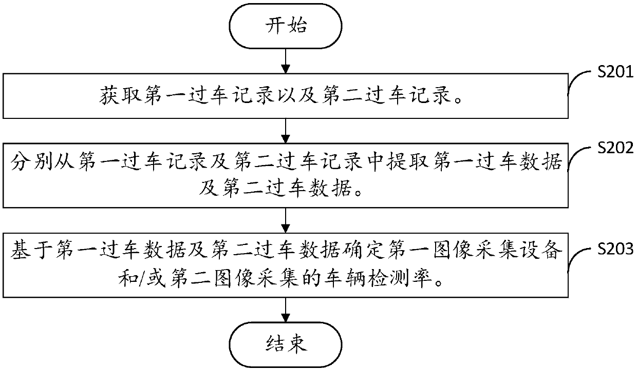
[0046] An embodiment of the present invention provides a method for determining a vehicle detection rate, which is used for determining a vehicle detection rate. see figure 2 , is a flowchart of a vehicle detection rate method provided by an embodiment of the present invention. The vehicle detection rate method includes:
[0047] Step S201: Obtain the first vehicle passing record and the second vehicle passing record.
[0048] Wherein, the first vehicle passing record and the second vehicle passing record are respectively collected by the first image acquisition device and the second image acquisition device located in the same test scene.
[0049] It should be noted that the vehicle passing records include multiple passing pictures and passing data; the passing pictures are the pictures taken by the image acquisition equipment, and the passing data contains multiple sets of passing information, and each set of passing information corresponds to a Passing vehicle pictures,...
no. 2 example
[0099] see Figure 7 , Figure 7 It is a flow chart of a method for determining a vehicle detection rate provided by a preferred embodiment of the present invention. It should be noted that the basic principles and technical effects of the method for determining the detection rate of vehicles provided in this embodiment are the same as those of the above-mentioned embodiments. corresponding content in the example. The vehicle detection rate determination method includes:
[0100] Step S701: Obtain at least three sets of passing records.
[0101] Among them, at least three sets of passing records are respectively collected by multiple image acquisition devices located in the same test scene.
[0102] Step S702: extract the passing data from each group of passing records.
[0103] Step S703: Determining any one of the at least three groups of passing data as the first passing data, and determining the set of all other passing data in the at least three groups as the second ...
no. 3 example
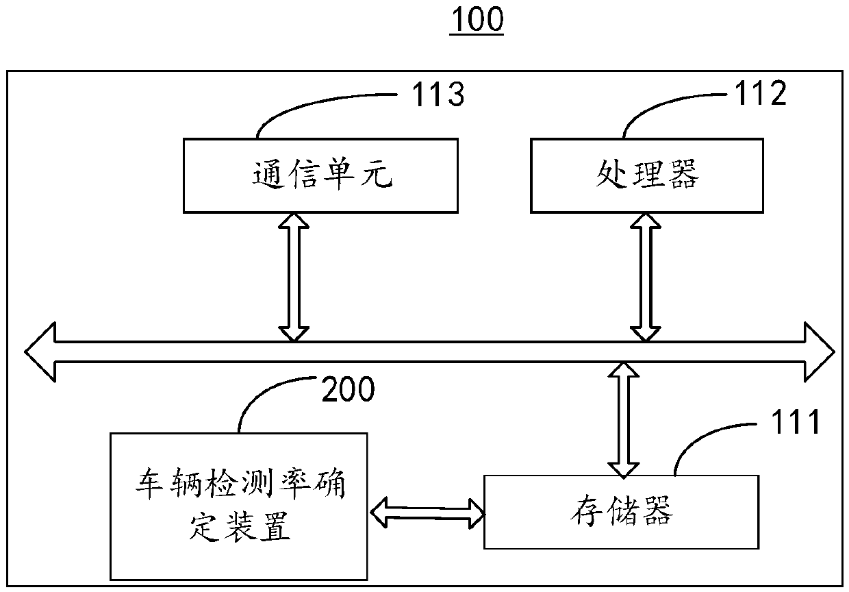
[0109] see Figure 8 , Figure 8 A functional block diagram of a vehicle detection rate determining device 200 provided in a preferred embodiment of the present invention. It should be noted that the vehicle detection rate determination device 200 provided in this embodiment has the same basic principles and technical effects as those of the above-mentioned embodiments. Corresponding content in the embodiment. The vehicle detection rate determination device 200 includes: a vehicle passing record acquisition unit 210 , a vehicle passing data extraction unit 220 and a vehicle detection rate determination unit 230 .
[0110] In a preferred embodiment, the vehicle passing record obtaining unit 210 is configured to obtain a first vehicle passing record and a second vehicle passing record.
[0111] It can be understood that, in a preferred embodiment, the vehicle passing record acquisition unit 210 can be used to execute step S201.
[0112] The vehicle passing data extracting un...
PUM
 Abstract
Description
Claims
Application Information