
A clamping tool for PCB board processing
A PCB board, clamping tooling technology, applied in clamping devices, metal processing equipment, metal processing mechanical parts, etc., can solve problems affecting processing accuracy, processing errors, etc., and achieve the effect of avoiding displacement deviation
- Summary
- Abstract
- Description
- Claims
- Application Information
AI Technical Summary
Problems solved by technology
Method used
Image

Examples
Embodiment
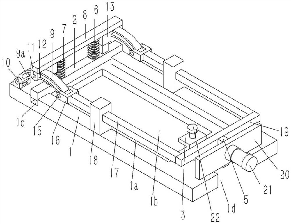
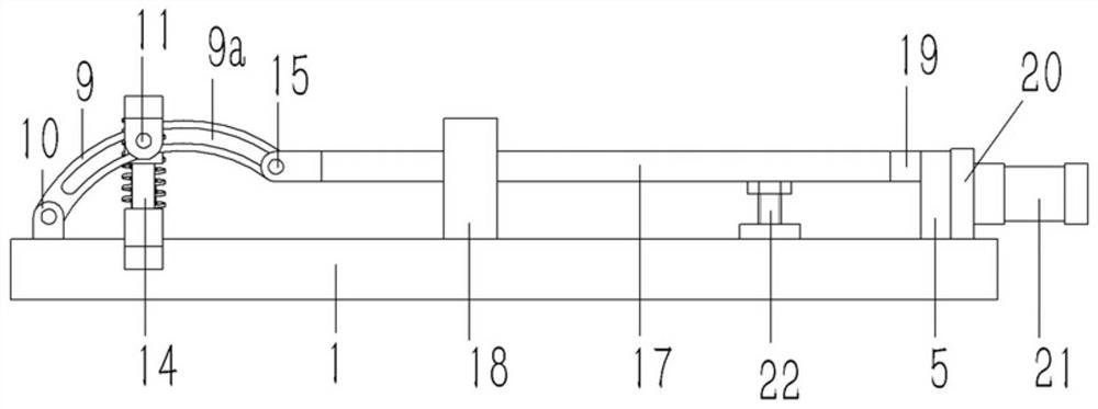
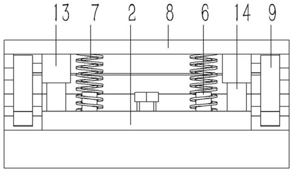
[0020] Example: see Figures 1 to 4 As shown, a clamping tool for PCB board processing includes a clamping platform 1. A rectangular concave platform 1a is formed on the upper end surface of the clamping platform 1. The upper end surface of the clamping platform 1 on the left side is formed with a longitudinal groove 1c communicating with the concave table 1a, and the middle part of the right side of the clamping platform 1 is formed with a rectangular notch 1d. A longitudinal bead 2 is inserted into the longitudinal groove 1c, and an L-shaped push block 3 is inserted on the right side of the concave table 1a of the clamping platform 1, and a push rod 4 is fixed on the right end surface of the push block 3, and the push rod 4 is inserted into the Connected to the right side wall of the concave table 1a, the right end of the push rod 4 is inserted into the notch 1d of the clamping platform 1;
[0021] A number of connecting columns 6 are fixed on the upper end surface of the b...
PUM
 Abstract
Description
Claims
Application Information