

Adjustable lift pedal
An adjustable, lifting unit technology, used in medical science, surgery, diagnosis, etc., to achieve the effect of improving stability, convenient and simple adjustment, and increased height adjustability
- Summary
- Abstract
- Description
- Claims
- Application Information
AI Technical Summary
Problems solved by technology
Method used
Image

Examples
Embodiment 1
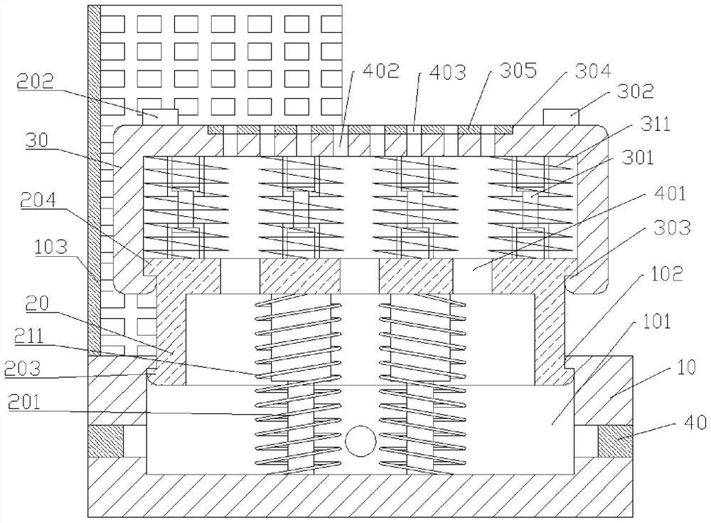
[0034] Embodiment 1 is basically as attached figure 1 Shown: adjustable lifting pedal, including stable platform 10, the first lifting unit, the second lifting unit and four negative pressure machines 40, the center of the stable platform 10 is vertically provided with a chute 101, the top of the chute 101 A first flange 102 is integrally formed on the inner wall, and the first flange 102 is annular and extends toward the center of the cross-section of the stabilizing platform 10 .
[0035]The first lifting unit includes a first sliding cover 20, two first telescopic oil cylinders 201, two first extension springs 211 and a first switch 202 electrically connected to the two first telescopic oil cylinders 201; the first sliding cover 20 is in the shape of " П" type, the first sliding cover 20 is vertically arranged in the chute 101, and the outer wall of the lower end of the first sliding cover 20 is provided with a first raised bar 203 that can be offset against the first flang...
Embodiment 2
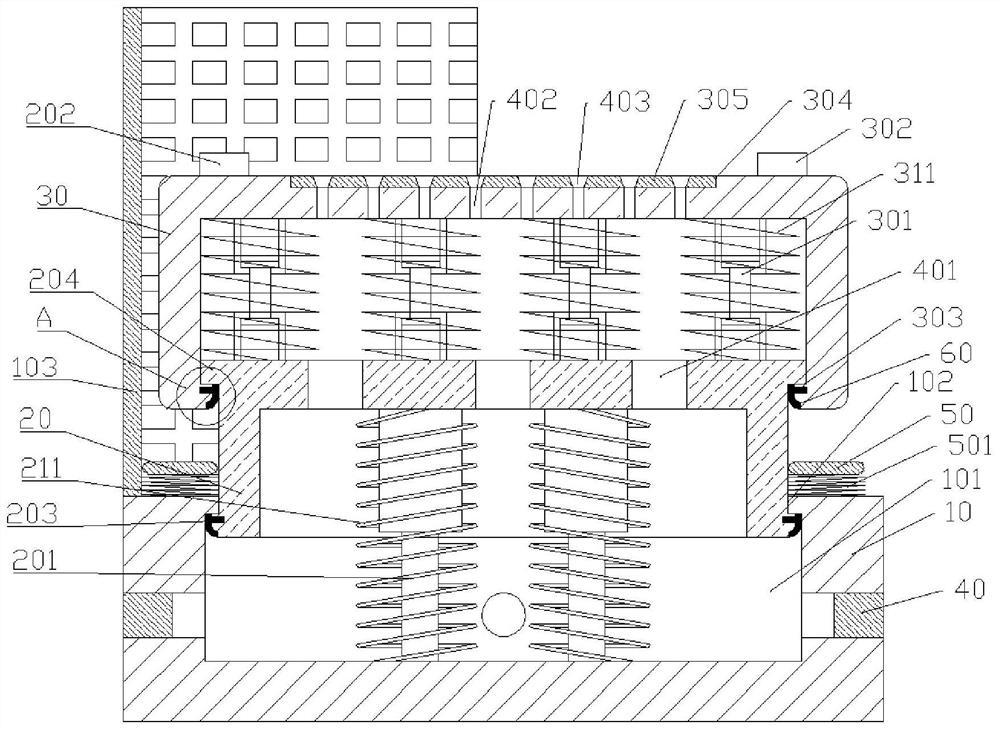
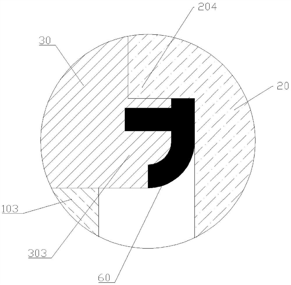
[0047] The difference between embodiment 2 and embodiment 1 is that embodiment 2 is basically as attached figure 2 And attached image 3 As shown, it also includes a support unit, the support unit includes a support ring 50 and a number of springs 501, the support ring 50 is coaxially sleeved outside the first sliding cover 20, and the spring 501 is vertically arranged, the upper end of the spring 501 and the support ring 50 The lower surface is welded, the lower end of the spring 501 is welded to the upper surface of the stable platform 10 , and the upper surface of the support ring 50 can be against the lower end surface of the second sliding cover 30 .
[0048] In addition, graphite strips 60 are provided on the side of the first protruding bar 203 close to the inner wall of the chute 101 and on the side of the third protruding bar 303 close to the side wall of the first sliding cover 20; meanwhile, the third through hole 403 is in the form of figure 1 The funnel shape sh...
Embodiment 3
[0053] The difference between embodiment 3 and embodiment 2 is that embodiment 3 is basically as attached Figure 4 As shown, it also includes an infrared sensor 70 and several lighting lamps 701. The infrared sensor 70 is buckled and installed on the upper end of the enclosure 103, and the infrared sensor 70 is arranged on the right side of the enclosure 103. The infrared sensor 70 and the The first sliding cover 20 and the second sliding cover 30 are opposite, and the sensing range of the infrared sensor 70 is greater than 1.5 times the surface area of the upper surface of the second sliding cover 30; on the surface, and several lighting lamps 701 are evenly distributed on the enclosure 103; at the same time, the lighting lamps 701 are connected with the infrared sensor 70 signal, when the infrared sensor 70 sends out the induction pulse signal, the lighting lamps 701 are turned on synchronously, when the infrared sensor 70 When the induction pulse signal is no longer sent...
PUM
 Abstract
Description
Claims
Application Information