Angle-adjustable photographic lamp

A photography light and angle adjustment technology, which is applied in the field of photography lights, can solve problems such as inability to ensure accurate irradiation of photography lights, affecting the effect of taking pictures, and low adjustment accuracy

Active Publication Date: 2020-10-23
SHENZHEN RIHUIDA ELECTRONICS CO LTD
View PDF11 Cites 0 Cited by
  • Summary
  • Abstract
  • Description
  • Claims
  • Application Information

AI Technical Summary

Problems solved by technology

[0002] Photographic light is an essential camera equipment, used for light irradiation when taking pictures, in order to achieve a good photo effect, it is generally necessary to adjust the angle of the photographic light, the existing photographic lights are all placed on the bracket, through The bracket adjusts the height and shooting angle. However, the accuracy of adjustment through the bracket is generally not high. It can be adjusted to a rough position and cannot ensure the precise irradiation of the photography light. To a certain extent, it will still affect the effect of taking pictures. In order to achieve For a better photo effect, it is urgent to design a photography light that can finely adjust the light angle

Method used


Image

  • Angle-adjustable photographic lamp
  • Angle-adjustable photographic lamp
  • Angle-adjustable photographic lamp

Examples


Embodiment Construction

[0030] In order to enable those skilled in the art to better understand the technical solution of the present invention, the present invention will be described in detail below in conjunction with the accompanying drawings. The description in this part is only exemplary and explanatory, and should not have any limiting effect on the protection scope of the present invention. .

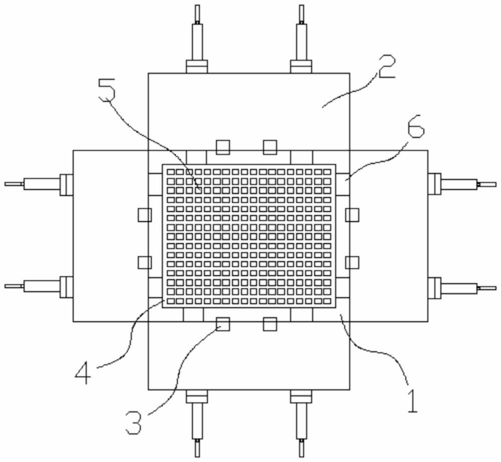
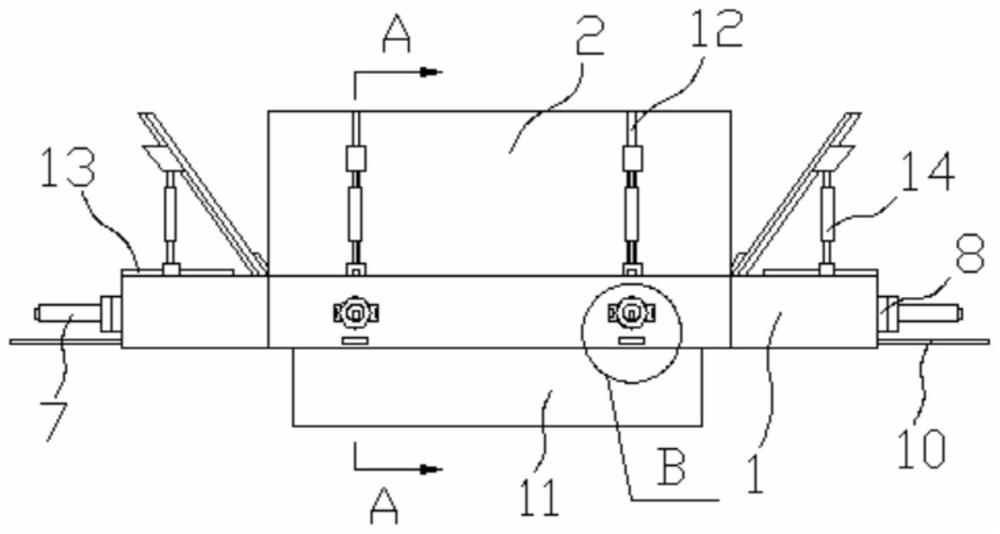
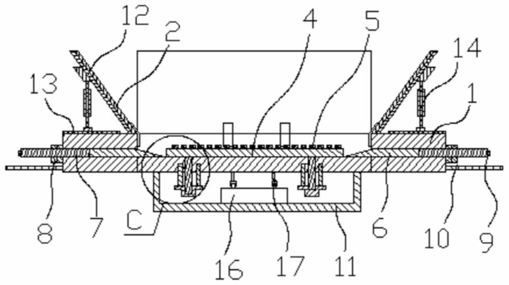
[0031] Such as Figure 1-4 As shown, the specific structure of the present invention is: an angle-adjustable photographic lamp, comprising a mounting frame 1 with a front opening, and four side plates of the mounting frame 1 except the rear side plate are connected by hinges 3 The baffle plate 2, the housing 11 is arranged on the rear side of the installation frame, the lamp board 4 is installed in the installation frame 1, the lamp bead 5 is embedded in the front side of the lamp board 4, and the lamp bead 5 is connected with the lamp The circuit board in the board is electrically connected, and the ...


PUM


Abstract

The invention relates to an angle-adjustable photographic lamp. The lamp comprises a mounting frame with a front opening, four side plates, except a rear side plate, of the mounting frame are connected with baffles through hinge pieces; a shell is arranged behind the mounting frame; a lamp panel is mounted in the mounting frame; lamp beads are embedded into the front side of the lamp panel. The lamp beads are electrically communicated with a circuit board in the lamp panel; the rear side of the mounting frame is provided with a mounting device capable of enabling the lamp panel to be attachedto a rear side plate in the mounting frame backwards. A circuit board of the lamp panel is electrically communicated with a power distribution controller in the shell; angle adjusting inclined blockscapable of penetrating into the mounting frame are arranged on the four side plates, except the rear side plate, of the mounting frame, the angle adjusting inclined blocks can be inserted between thelamp panel and the rear side plate of the mounting frame, and each angle adjusting inclined block is connected with a single inclined block pushing structure. Through the angle adjusting inclined blocks arranged on the side frames of the mounting frame, the mounting angle of the lamp panel and the mounting frame can be adjusted, then lamplight can be adjusted again, and the effect of accurate adjustment is achieved.

Description

technical field [0001] The invention relates to the field of photographic equipment, in particular to an angle-adjustable photographic lamp. Background technique [0002] Photographic light is an essential camera equipment, used for light irradiation when taking pictures, in order to achieve a good photo effect, it is generally necessary to adjust the angle of the photographic light, the existing photographic lights are all placed on the bracket, through The bracket adjusts the height and shooting angle. However, the accuracy of adjustment through the bracket is generally not high. It can be adjusted to a rough position and cannot ensure the precise irradiation of the photography light. To a certain extent, it will still affect the effect of taking pictures. In order to achieve For a better photo effect, it is urgent to design a photography light that can finely adjust the light angle. Contents of the invention [0003] The purpose of the present invention is to provide a...

Claims


Application Information

Patent Timeline
Patent Type & Authority Applications(China)
IPC IPC(8): G03B15/05
CPCG03B15/05
Inventor 蓸军梁喜富李金秋李国春
Owner SHENZHEN RIHUIDA ELECTRONICS CO LTD
Why Eureka
Try Eureka