Automatic pitching device

A ball throwing device and automatic technology, applied in the direction of cleaning hollow objects, pipes/pipe joints/pipe fittings, chemical instruments and methods, etc., can solve the problems affecting the flow rate of crude oil and normal oil delivery, etc. , the effect of simplifying the structure

Pending Publication Date: 2020-10-27
CHINA UNIV OF PETROLEUM (BEIJING) +1
View PDF0 Cites 0 Cited by
  • Summary
  • Abstract
  • Description
  • Claims
  • Application Information

AI Technical Summary

Problems solved by technology

As the paraffin sticks to the wall of the crude oil delivery pipe, it seriously affects the crude oil flow rate and normal oil delivery

Method used


Image

  • Automatic pitching device
  • Automatic pitching device
  • Automatic pitching device

Examples


Embodiment Construction

[0036] In order to have a clearer understanding of the technical features, purpose and effects of the present invention, the specific implementation, structure, features and functions of the automatic ball throwing device proposed by the present invention will be described in detail below in conjunction with the accompanying drawings and preferred embodiments. In addition, through the description of the specific implementation, the technical means and effects of the present invention to achieve the intended purpose can be understood more deeply and specifically. However, the attached drawings are only for reference and illustration, and are not used to limit the present invention. .

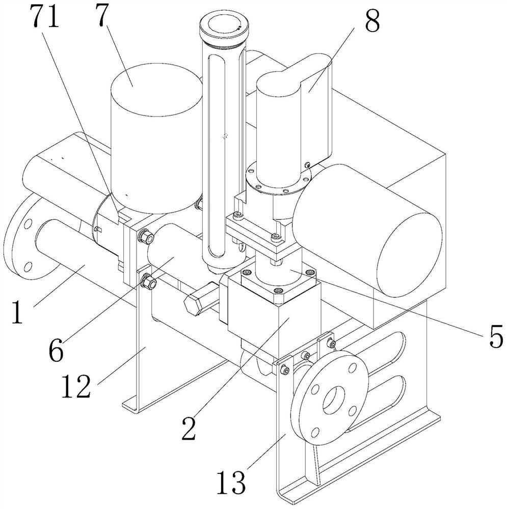
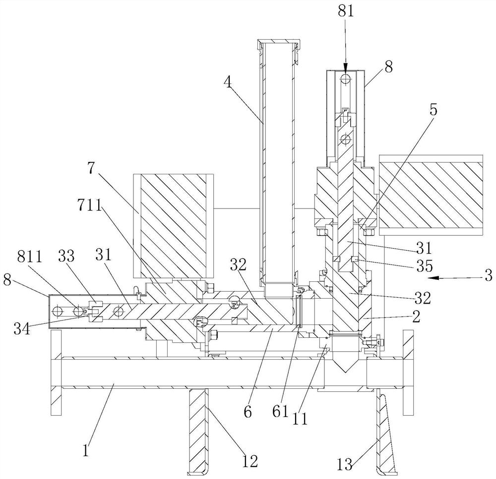
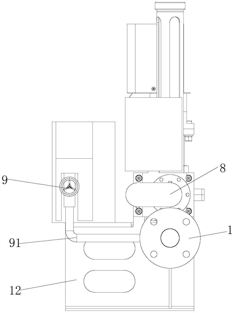
[0037] figure 1 It is a perspective view of the automatic pitching device of the present invention. figure 2 It is a sectional view of the automatic ball throwing device of the present invention. image 3 It is the left view of the automatic pitching device of the present invention. Figure 4...


PUM


Abstract

The invention provides an automatic pitching device. The automatic pitching device comprises a conveying pipeline, a three-way pipeline seat and a ball storing tube; a connector is upwards convexly formed in the side wall of the conveying pipeline in the radial direction; a first end opening in the lower end of the three-way pipeline seat is connected with the connector in a sealed mode, and a vertical guide sleeve is inserted into a second end opening in the upper end of the three-way pipeline seat in the vertical direction in a sealed mode; a horizontal guide sleeve is inserted into a thirdend opening in one side of the three-way pipeline seat in a sealed mode, and the horizontal guide sleeve is parallel to the conveying pipeline; the vertical guide sleeve and the horizontal guide sleeve are each internally provided with a piston rod capable of moving back and forth under driving by a power device; and the ball storing tube is used for being filled with paraffin removal balls and mounted on the horizontal guide sleeve in the vertical direction, an inner cavity of the ball storing tube communicates with an inner cavity of the horizontal guide sleeve, the paraffin removal balls inthe ball storing tube can enter the horizontal guide sleeve, the piston rod in the horizontal guide sleeve can push the paraffin removal balls to enter the three-way pipeline seat, and the paraffin removal balls can be downwards pushed by the piston rod in the vertical guide sleeve into the conveying pipeline. The structure is simplified, and pitching clearing work of the pipeline is facilitated.

Description

technical field [0001] The invention belongs to the field of oil exploitation, and in particular relates to an automatic ball throwing device. Background technique [0002] In oil extraction, the produced petroleum crude oil contains paraffin to varying degrees, resulting in the precipitation of paraffin to varying degrees during the transportation of crude oil in oil pipelines. As the paraffin sticks to the wall of the crude oil delivery pipe, it seriously affects the crude oil flow rate and normal oil delivery. For this reason, it is necessary to throw balls into the crude oil pipeline to remove wax to ensure the smooth flow of the pipeline. [0003] In view of this, the inventor has developed an automatic ball throwing device based on the experience in production design in this field and related fields, in order to solve the problems in the prior art. Contents of the invention [0004] The object of the present invention is to provide an automatic ball throwing device...

Claims


Application Information

Patent Timeline
Patent Type & Authority Applications(China)
IPC IPC(8): B08B9/057F16L55/24
CPCB08B9/057B08B2209/053F16L55/24
Inventor 顾岱鸿刘广峰雒亮
Owner CHINA UNIV OF PETROLEUM (BEIJING)
Why Eureka
Try Eureka