Coal mining machine positioning device

A technology of positioning device and shearer, which is applied in the directions of measuring devices, instruments, surveying and mapping, and navigation, etc., can solve the problems of inconvenient direction adjustment, low practicability, and difficulty in applying automatic control, etc. Precise positioning in three-dimensional space, which is conducive to the effect of automatic control

Inactive Publication Date: 2021-01-26
高洪江
View PDF1 Cites 0 Cited by
  • Summary
  • Abstract
  • Description
  • Claims
  • Application Information

AI Technical Summary

Problems solved by technology

[0003] After retrieval, the patent publication number is CN210919041U, which discloses a shearer positioning device, which transmits light and sound through the alarm lamp and alarm installed inside the multi-function pole, so that outsiders can better find the position of the shearer However, during its use, 1, due to the need to change the positioning direction during positioning, it is necessary to reinstall the locator body, which is not convenient for users to operate; 2, and if the height needs to be adjusted during the adjustment process, it is necessary to increase the support Frame body, but it is inconvenient to find a support frame body on site, it is not convenient for users to adjust the direction, and the practicability is low. 3. When adjusting the angle, the existing locator cannot realize free adjustment in three-dimensional space; 4. Now When some locators are adjusted, the adjusted height or angle value cannot be accurately determined, and the value is difficult to obtain with measuring instruments, which brings difficulties to positioning, and it is difficult to apply automatic control

Method used


Image

  • Coal mining machine positioning device
  • Coal mining machine positioning device
  • Coal mining machine positioning device

Examples


Embodiment

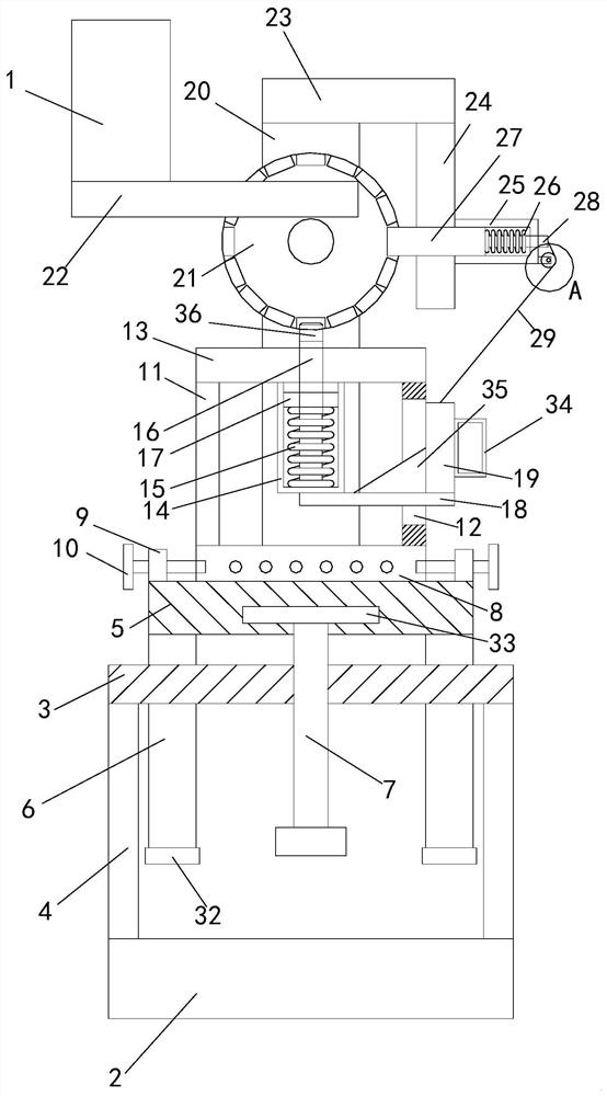
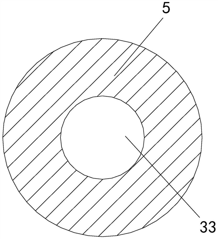
[0032] see Figure 1-5, a positioning device for a coal mining machine, comprising a locator body 1 and a bottom plate 2, a middle plate 3 is arranged on the upper side of the bottom plate 2, and a support plate 4 is fixedly connected to the bottom left part and the bottom right part of the middle plate 3, The bottom of each support plate 4 is fixedly connected with the top of the bottom plate 2, the upper side of the middle plate 3 is provided with a movable plate 5, and the four corners of the bottom of the movable plate 5 are fixedly connected with sliding shafts 6, and each sliding shaft 6 The bottom ends pass through the middle part of the middle plate 3 from the top of the middle plate 3, and the bottom ends of each sliding shaft 6 are fixedly connected to the limit boss 32; the movement range of the slide shaft 6 is limited by the limit boss 32 to avoid sliding. After the shaft 6 moves too much, it is separated from the middle plate 3, so as to further improve the pract...


PUM


Abstract

The invention relates to the technical field of coal mining machines, in particular to a coal mining machine positioning device which comprises a positioning instrument body and a bottom plate, a middle plate is arranged on the upper side of the bottom plate, supporting plates are fixedly connected to the left portion and the right portion of the bottom end of the middle plate, the bottom ends ofthe supporting plates are fixedly connected with the top end of the bottom plate, and a movable plate is arranged on the upper side of the middle plate. Sliding shafts are fixedly connected to the areas of the four corners of the bottom end of the movable plate, the bottom ends of the sliding shafts penetrate through the middle of the middle plate from the top end of the middle plate, the bottom end of the movable plate is rotationally connected with a screw, and the bottom end of the screw penetrates through the middle of the middle plate from the top end of the middle plate in a screwed mode, the middle portion of the top end of the movable plate is rotationally connected with a rotating column, fixed plates are fixedly connected to the left portion and the right portion of the top end of the movable plate, positioning screws are screwed in the middles of the fixed plates, and a first supporting plate and a second supporting plate are fixedly connected to the left portion and the right portion of the top end of the rotating column correspondingly. The device is convenient for a user to operate, convenient for the user to adjust the direction and relatively high in practicability.

Description

technical field [0001] The invention relates to the technical field of coal shearers, in particular to a positioning device for coal shearers. Background technique [0002] The coal shearer is a kind of equipment used for coal mining. During the use of the coal shearer, the position of the coal mining needs to be positioned to reduce the phenomenon of digging deviation. [0003] After retrieval, the patent publication number is CN210919041U, which discloses a shearer positioning device, which transmits light and sound through the alarm lamp and alarm installed inside the multi-function pole, so that outsiders can better find the position of the shearer However, during its use, 1, due to the need to change the positioning direction during positioning, it is necessary to reinstall the locator body, which is not convenient for users to operate; 2, and if the height needs to be adjusted during the adjustment process, it is necessary to increase the support Frame body, but it is...

Claims


Application Information

Patent Timeline
Patent Type & Authority Applications(China)
IPC IPC(8): G01C21/00
CPCG01C21/00
Inventor 高洪江
Owner 高洪江
Why Eureka
Try Eureka