
Novel abdominal retractor for operation
A technique for surgery and abdomen, which is applied in surgery, medical science, pumping and delivery systems, etc. It can solve problems such as simple structure, patient injury, and incision opening, and achieves the effect of convenient operation, reasonable structure, and reduced workload
- Summary
- Abstract
- Description
- Claims
- Application Information
AI Technical Summary
Problems solved by technology
Method used
Image

Examples
Embodiment
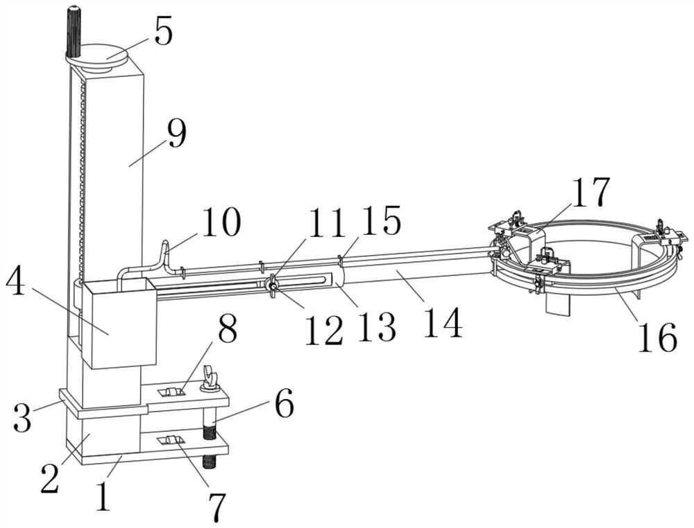
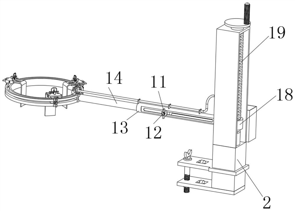
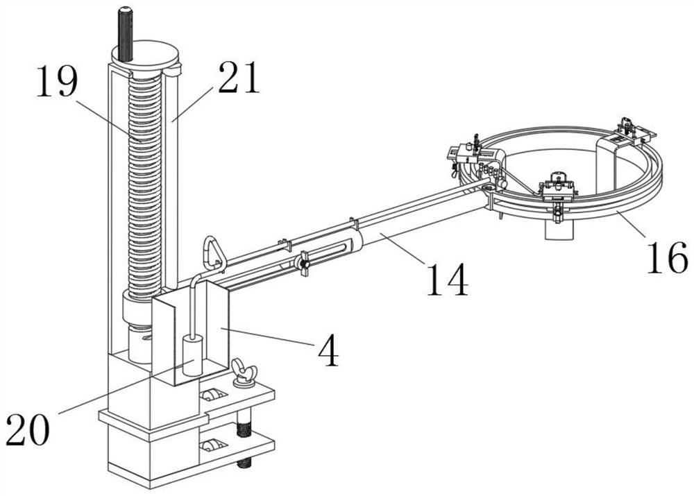
[0043] Example: Reference Figure 1-10 A new type of abdominal retraction device for surgery is shown, including a base plate 1, the top of the base plate 1 is fixedly connected with a column 2, and the column 2 is provided with a U-shaped support plate 9, and the column 2 can be any one in the prior art The steel column structure is fixedly connected with the bottom plate 1 by welding.
[0044] The top of the column 2 is rotatably connected with a threaded column 19, the threaded column 19 is screwed with a threaded sleeve 18, and the side wall of the threaded sleeve 18 is fixedly connected with a support column 13, and the support column 13 and the threaded sleeve 18 can be existing Welding connection method in technology.
[0045] One end of support column 13 is provided with sliding column 14, and one end of sliding column 14 is provided with annular bar 16, and the top of annular bar 16 is provided with annular chute 33, and the side wall of annular bar 16 is provided wi...
PUM
 Abstract
Description
Claims
Application Information