Needle bar self-locking mechanism

A needle bar, self-locking technology, applied in the field of embroidery machines, can solve the problems of difficult needle bar self-locking, axial fall off, needle bar damage to mechanical parts, etc.

Active Publication Date: 2021-02-26
ZHUJI MAYA ELECTRIC APPLIANCE MACHINERY
View PDF10 Cites 0 Cited by
  • Summary
  • Abstract
  • Description
  • Claims
  • Application Information

AI Technical Summary

Problems solved by technology

However, this solution still cannot lock the position of the needle bar during the working process, and it is difficult to realize the self-locking of the needle bar, and it is easy to fall off in the axial direction during the clutch switching process of the needle bar, causing the needle bar to fall and damage other mechanical parts. part

Method used


Image

  • Needle bar self-locking mechanism
  • Needle bar self-locking mechanism
  • Needle bar self-locking mechanism

Examples


Embodiment Construction

[0026] The present invention will be further described below in conjunction with the accompanying drawings.

[0027] Such as Figure 1-4 as shown,

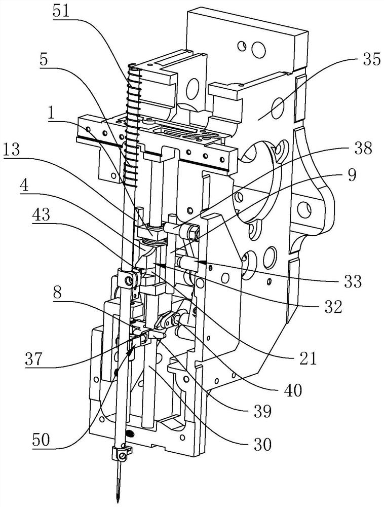
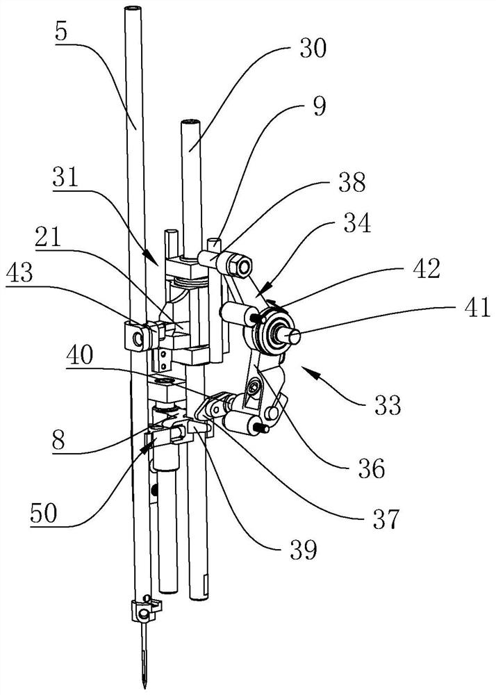
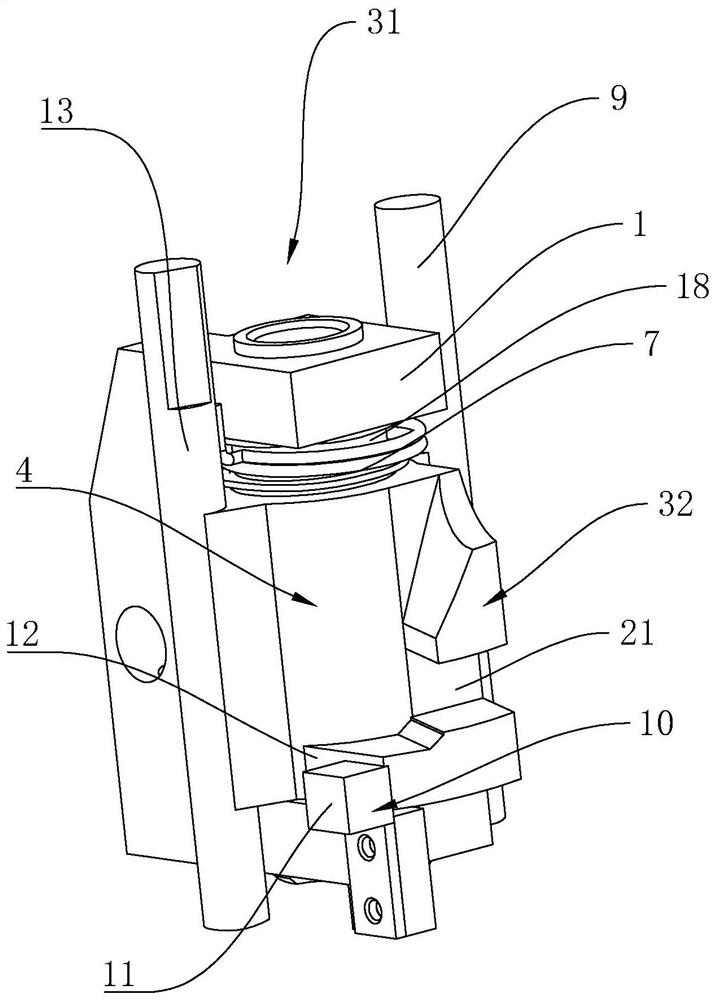
[0028] A needle bar self-locking mechanism, including a guide rod 30 vertically fixedly arranged on the machine head housing 35, on which a presser foot driver 8 and a needle bar driver 31 are axially movable, and the needle bar The driver 31 and the presser foot driver 8 are spaced apart in the vertical direction, and the needle bar driver 31 is located above the presser foot driver 8, and the needle bar driver 31 is connected to the needle bar 5 through a clutch structure 32. Between the foot driver 8 and the needle bar driver 31 is provided a linkage type clutch control structure 33 which is powered by the presser foot driver 8 to control the action of the clutch structure 32. The needle bar 5 is axially movable through the needle bar frame and An axial anti-off structure 50 is provided between the two, and a needle bar jacki...


PUM


Abstract

The invention belongs to the technical field of embroidery machines, and particularly relates to a needle bar self-locking mechanism. The needle bar self-locking mechanism comprises a guide rod vertically and fixedly arranged on a machine head shell, wherein a presser foot driver and a needle bar driver are movably arranged on the guide rod in the axial direction, the needle bar driver and the presser foot driver are arranged in a spaced mode in the vertical direction, the needle bar driver is located above the presser foot driver, and the needle bar driver is connected with a needle bar through a clutch structure. According to the needle bar self-locking mechanism, a linkage relationship is established between the presser foot driver and the needle bar driver, and the clutch structure between the needle bar driver and the needle bar is controlled by utilizing the position change of the presser foot driver, so that the separation and connection of the needle bar are realized; and afterthe needle bar driver is separated from the needle bar, a needle bar jacking structure lifts the needle bar so as to lock the needle bar and prevent the needle bar from falling. Due to the arrangement of an axial anti-disengagement structure, the needle bar cannot be disengaged from a needle bar frame.

Description

technical field [0001] The invention belongs to the technical field of embroidery machines and relates to a needle bar self-locking mechanism. Background technique [0002] Computerized embroidery machine is the most advanced embroidery machine in the contemporary era. It can achieve high-speed and high-efficiency traditional manual embroidery, and can also achieve "multi-level, multi-functional, uniform and perfect" that cannot be achieved by manual embroidery. Requirements, it is an electromechanical product that embodies a variety of high-tech. The needle bar mechanism is a very important part in the computerized embroidery machine. Generally, the needle bar driver is used to drive the needle bar to reciprocate up and down to perform needle drop. If it falls, the position of the needle bar cannot be locked, and it is difficult to realize the self-locking of the needle bar, and it is easy to fall off in the axial direction during the clutch switching process of the needle...

Claims


Application Information

Patent Timeline
Patent Type & Authority Applications(China)
IPC IPC(8): D05C11/06D05C9/20
CPCD05C11/06D05C9/20
Inventor 张丁元魏大江陈信宝王亮王立庆周伟
Owner ZHUJI MAYA ELECTRIC APPLIANCE MACHINERY
Why Eureka
Try Eureka