A Shipborne Temporary Emergency Shipwreck Position Indicating Device

A temporary, ship-borne technology, used in ship salvage, transportation and packaging, special-purpose ships, etc., can solve problems such as short working hours, wrong position changes, and buoys cannot provide overturning positions, and achieves arrangement rules and neatness, winding. maximized effect

Active Publication Date: 2021-12-28
JIMEI UNIV
View PDF6 Cites 0 Cited by
  • Summary
  • Abstract
  • Description
  • Claims
  • Application Information

AI Technical Summary

Problems solved by technology

[0003] However, when the sunken ship is far away from the shore, the sea condition is bad or at night, and the visibility is poor, it is difficult to deploy the sunken ship's position indicating mark for the sunken ship in time. Due to the characteristics of wave drift, it is impossible to accurately identify the position of the sunken ship for a long time
[0004] Existing ship-borne temporary emergency shipwreck position indicating devices exist in the form of buoys, but because the buoys are floating on the water surface, there is a possibility of movement, and the position changes caused by floating will produce wrong guidance, causing passing ships to Avoiding the buoys and entering from the correct overturning position will cause a second overturning, and some buoys will be connected to the hull through ropes, but this method will also bring the buoys down when the overturning position is deep, so the buoys cannot Provide approximate overturned location, resulting in low collection efficiency

Method used


Image

  • A Shipborne Temporary Emergency Shipwreck Position Indicating Device
  • A Shipborne Temporary Emergency Shipwreck Position Indicating Device
  • A Shipborne Temporary Emergency Shipwreck Position Indicating Device

Examples


Embodiment 1

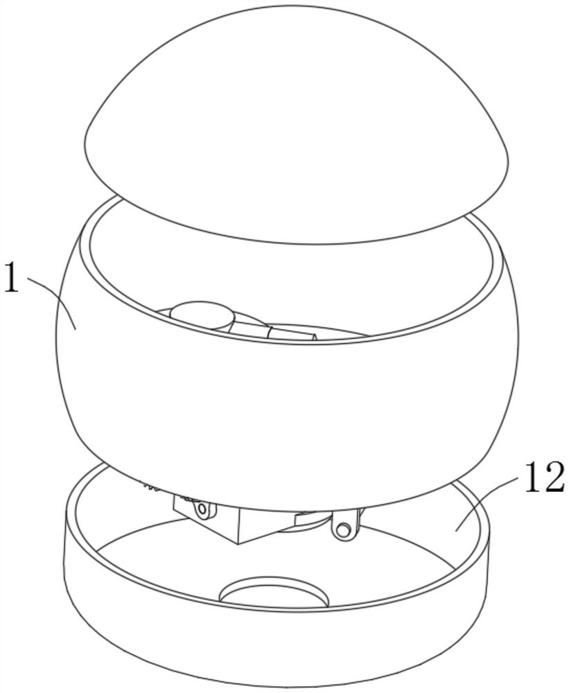
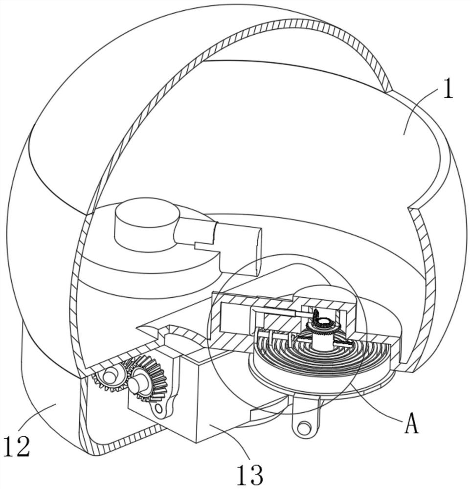
[0035] see Figure 1-4 and Figure 6-8 , the present invention provides a technical solution: a ship-borne temporary emergency shipwreck position indication device, including a suspension shell 1, the suspension shell 1 is a cavity structure for generating buoyancy, and the suspension shell 1 is composed of two parts , the two parts are convenient for installing equipment inside, and emergency search and rescue devices and warning devices, such as sirens, are installed in the cavity;

[0036] Rotationally connected to the rotating shaft 2 at the bottom of the suspension shell 1, the rotating shaft 2 is wound with a steel cable 3, the other end of the steel cable 3 is connected with a permanent magnet 4, and the permanent magnet 4 is convenient to be adsorbed on the hull when the hull capsizes above, and the whole equipment is set at a higher position on the hull, so that the hull can float when the hull capsizes, and it is connected with the hull flexibly, that is, connected ...

Embodiment 2

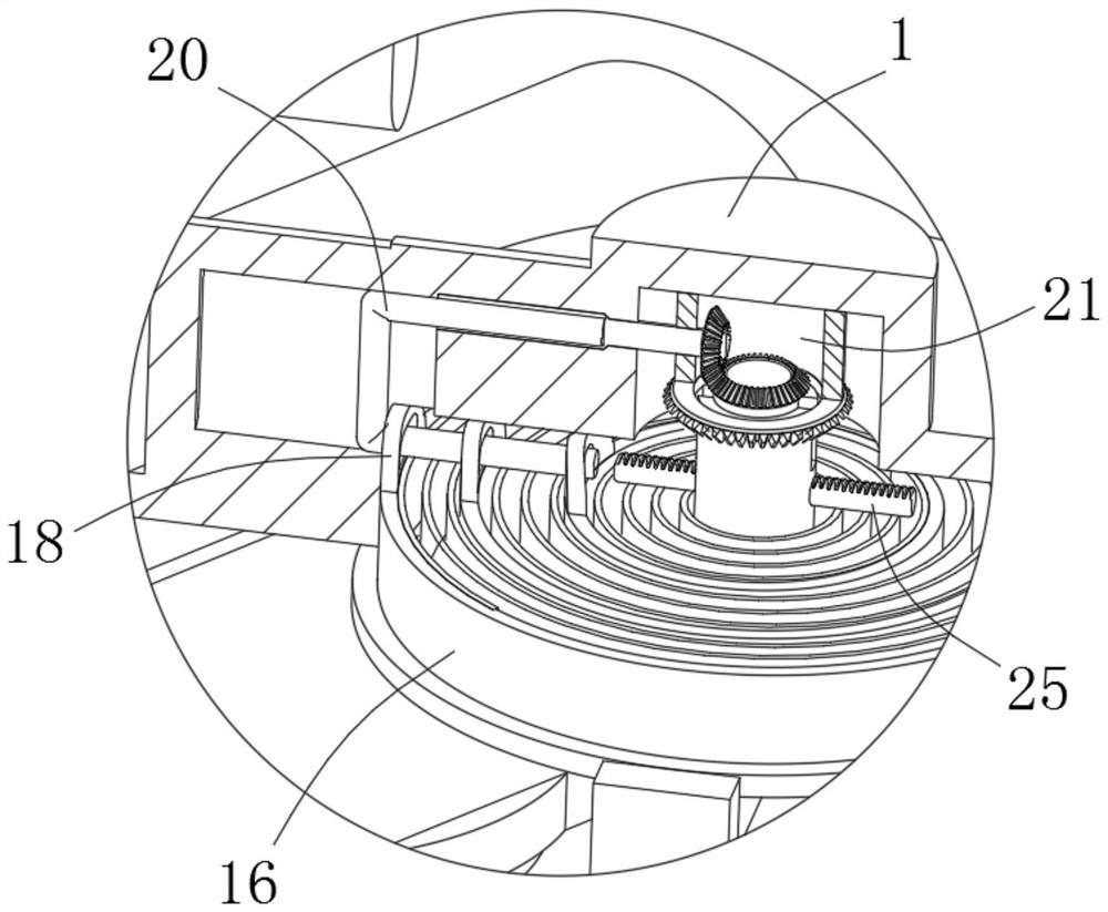
[0044] refer to Image 6 , Figure 8 and Figure 9 Embodiment 2 is described. This embodiment is a further description of Embodiment 1. The limiting mechanism 19 includes a first limit rod 20 that is slidably connected to the suspension shell 1. The function of the first limit rod 20 is to hold the part One end of the clockwork spring 17 does not rotate, thereby compressing the clockwork spring 17 or releasing the elastic potential energy, and the first stop rod 20 is slidably connected with the stop ring 18, and the inside of the stop ring 18 is a waist-shaped hole. The length of the length direction of the hole is greater than the cross-sectional diameter of the first limiting rod 20, the first limiting rod 20 is formed by connecting two parallel cylindrical rods through another cylindrical rod, and the bottom of the suspension housing 1 is also connected There is a fixed ring 21, the side wall of the fixed ring 21 runs through and is rotatably connected to a third drive s...

Embodiment 3

[0047] refer to Figure 4 , Figure 5 and Image 6 Embodiment 3 is described. This embodiment is a further description of Embodiment 2. The adjustment mechanism 14 includes a reciprocating screw rod 31 that is rotatably connected to the bottom of the suspension housing 1. The end of the reciprocating screw rod 31 is connected with a second A linkage gear 32, the rotating shaft 2 is fixedly connected with a first linkage gear 33 meshed with the second linkage gear 32, the reciprocating screw rod 31 is threaded with a threaded sleeve 34, and the inner shell 13 is fixedly connected There is a limiting plate 35 that limits the rotation of the threaded sleeve 34, and several reinforcing ribs 38 are arranged on the limiting plate 35, because when the reciprocating screw rod 31 rotates, the threaded sleeve 24 needs to be limited so that it can move along the reciprocating wire. The axial movement of the rod 34, the outer surface of the threaded sleeve 34 is fixedly connected with a...


PUM


Abstract

The invention discloses a ship-borne temporary emergency shipwreck position indication device, which comprises a suspension shell and a rotating shaft, a steel cable is wound around the rotating shaft, a permanent magnet is connected to the steel cable, and the bottom of the suspension shell is A first transmission shaft is connected, the first transmission shaft is connected with a second bevel gear and a third bevel gear, the suspension housing is connected with a second transmission shaft, and the energy storage device is arranged between the second transmission shaft and the third bevel gear. Between the suspension shells, the temporary emergency shipwreck position indicating device is installed on the ship. By setting a steel cable that can be wound to change the length at the bottom of the suspension shell, and a permanent magnet connected with the steel cable, when the hull capsizes, the suspension shell is suspended On the water surface, as a warning buoy, the permanent magnet will be adsorbed on the hull and continuously pull the steel cable. When the overturned position is not deep, it can accurately mark the overturned position. When the overturned position is too deep, due to the combined effect of magnetic adsorption and buoyancy The permanent magnet breaks away from the hull and starts to retract automatically, which can be automatically adjusted according to different situations.

Description

technical field [0001] The invention relates to the technical field of ship-borne emergency equipment, in particular to a ship-borne temporary emergency shipwreck position indicating device. Background technique [0002] After the ship capsizes and sinks, according to the water traffic management requirements, emergency shipwreck position indicating signs must be set up for the sunken ship as soon as possible to mark the existence and location of the sunken ship to warn passing ships to prevent collision accidents. [0003] However, when the sunken ship is far away from the shore, the sea condition is bad or at night, and the visibility is poor, it is difficult to deploy the sunken ship's position indicating mark for the sunken ship in time. Due to the characteristics of wave drift, it is impossible to accurately identify the position of the sunken ship for a long time. [0004] Existing ship-borne temporary emergency shipwreck position indicating devices exist in the form ...

Claims


Application Information

Patent Timeline
Patent Type & Authority Patents(China)
IPC IPC(8): B63B22/00B63B22/24B63C7/26
CPCB63B22/00B63B22/24B63C7/26
Inventor 甄荣
Owner JIMEI UNIV
Why Eureka
Try Eureka