Automatic structure for scissor type clamp

An automatic structure and fixture technology, applied in the direction of load hanging components, transportation and packaging, can solve the problems that the fixture cannot be standardized and the scenes are different.

Pending Publication Date: 2021-08-06
常州安兰克机械有限公司
View PDF0 Cites 0 Cited by
  • Summary
  • Abstract
  • Description
  • Claims
  • Application Information

AI Technical Summary

Problems solved by technology

[0004] Due to the wide variety of workpieces to be clamped and the different scenarios, fixtures cannot be standardized

Method used


Image

  • Automatic structure for scissor type clamp
  • Automatic structure for scissor type clamp
  • Automatic structure for scissor type clamp

Examples


Embodiment Construction

[0040] Now in conjunction with embodiment, accompanying drawing, automatic structure of the present invention is described further.

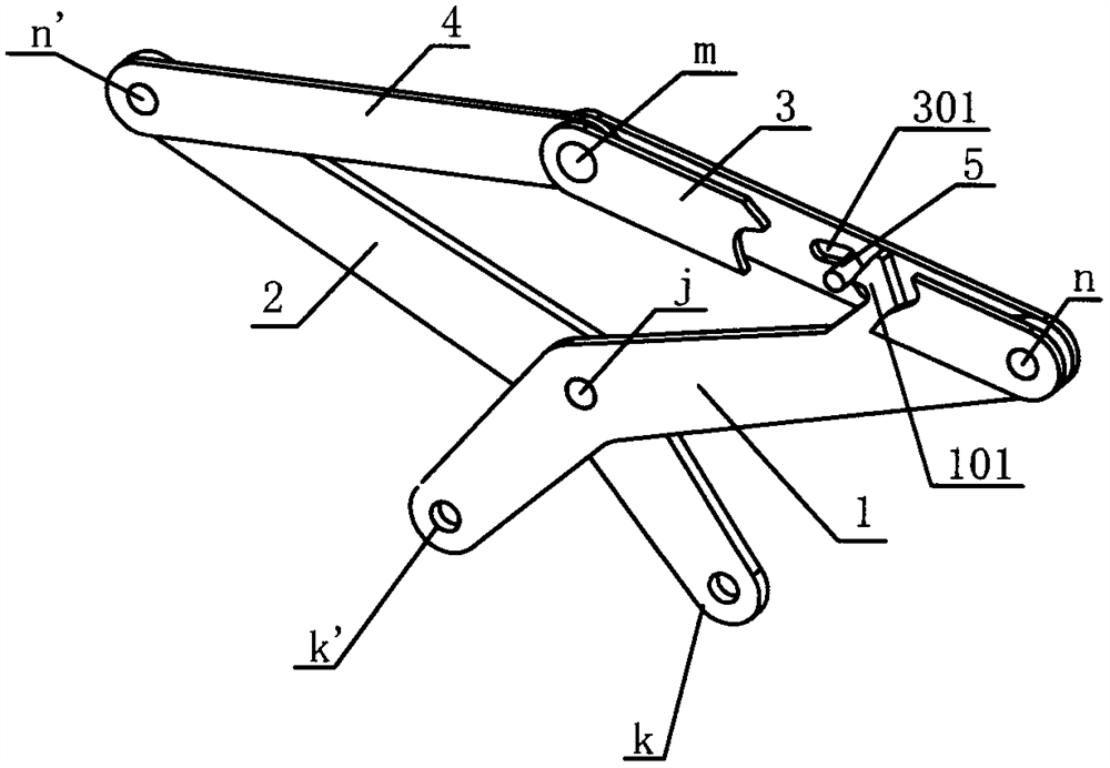
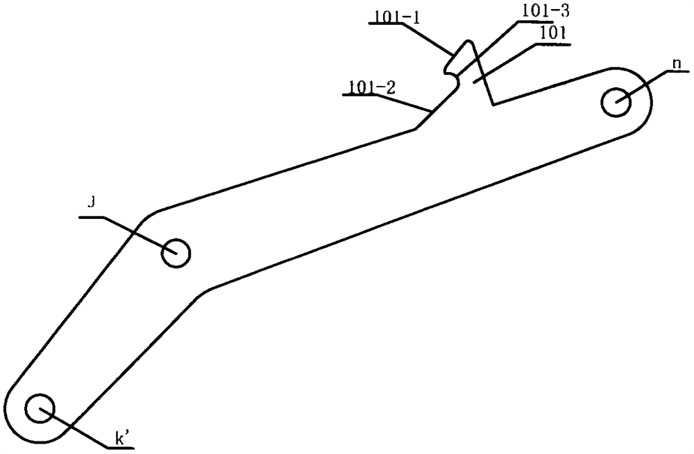
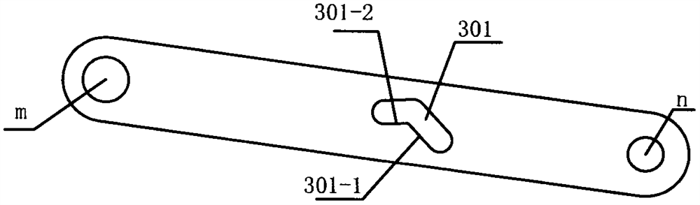
[0041] like figure 1 , Figure 5A kind of automatic structure for scissors fixture shown is characterized in that: comprise scissors arm 1, scissors arm 2, connecting rod 3, connecting rod 4, pin shaft 5, splint 6; Said scissors arm 1 and scissors arm 2 It is hinged at "j"; the upper end of scissors arm 1 is hinged at "n" with (two) connecting rods 3; the upper end of scissors arm 2 is hinged at "n'" with connecting rod 4; connecting rod 3, connecting rod 4 Hinged to each other at "m"; the two connecting rods 3 are respectively arranged on both sides of the connecting rod 4 and the scissor arm 1; there is a chute 301 on the connecting rod 3; the chute 301 is designed in an "L" shape The pin shaft 5 is limited in the chute 301 and can only roll in the chute 301; the scissor arm 1 is provided with a hook structure 101; the guide rod 601 of the ...


PUM


Abstract

The invention relates to an automatic clamp, in particular to a clamp of a scissor type structure. The invention provides another scissor type clamp grabbing and releasing mechanism, a hook-shaped structure is arranged on a scissor arm 1, a sliding groove is formed in a connecting rod 3, a pin 5 capable of sliding in the sliding groove is additionally arranged, and automatic opening and closing of the clamp are achieved through one-hand lifting and releasing actions. According to the structure, the scissor arm 1 and the connecting rod 3 can be directly formed by means of laser cutting, additional automatic devices do not need to be added, the operation process steps are completely consistent with those of an existing automatic clamp, and are not influenced by the size of a scissor type clamp, so that wide universality and economical efficiency are achieved.

Description

technical field [0001] The invention relates to a lifting fixture, in particular to a fixture with a scissor structure. Background technique [0002] At present, a large number of scissor fixtures are used to clamp workpieces in industries such as processing, assembly, and logistics at home and abroad. These clamps are generally equipped with a set of devices for controlling the opening and closing of the clamps to improve work efficiency. When operating the fixture, there is no need for personnel to touch or open the fixture, and the automatic opening and closing of the fixture is realized directly by using the self-weight of the fixture and the contact with the upper surface of the workpiece or the ground. The flow sequence during operation is: put down the fixture (to the workpiece) - lift the fixture (fixture clamping) - put down the fixture (to the target area) - lift the fixture (release the fixture). The sequence of "putting-lifting-putting-lifting" can be repeated ...

Claims


Application Information

Patent Timeline
Patent Type & Authority Applications(China)
IPC IPC(8): B66C1/42B66C1/44
CPCB66C1/422B66C1/442
Inventor 张文新杨浩葛国春
Owner 常州安兰克机械有限公司
Why Eureka
Try Eureka