Punching tool and stamping and punching method

A technology of punching and tooling, which is applied in the field of stamping and punching, can solve the problems of low precision, inability to guarantee the position and shape of the hole, and failure to meet the requirements of punching, so as to avoid the effect of placing and picking up parts

Pending Publication Date: 2022-01-07
VOYAH AUTOMOBILE TECH CO LTD
View PDF6 Cites 0 Cited by
  • Summary
  • Abstract
  • Description
  • Claims
  • Application Information

AI Technical Summary

Problems solved by technology

However, when the scheme of punching and reshaping is adopted, the hole is relatively close to the shaping area, and the deformation of the sheet metal during shaping is large, which will cause deformation of the punched hole during the wedge shaping process, and the position and shape of the hole Neither can be guaranteed, affecting the installation accuracy
[0003] Therefore, in order to ensure the punching accuracy, punching must first be shaped and then punched. However, because the side wall surface of the part near the punching hole is at a negative angle, the punch and the die sleeve will interfere, and the existing punching die and process guide the accuracy. Very low, usually used for flanging and shaping process content, can not meet the requirements of punching

Method used


Image

  • Punching tool and stamping and punching method
  • Punching tool and stamping and punching method
  • Punching tool and stamping and punching method

Examples


Embodiment 1

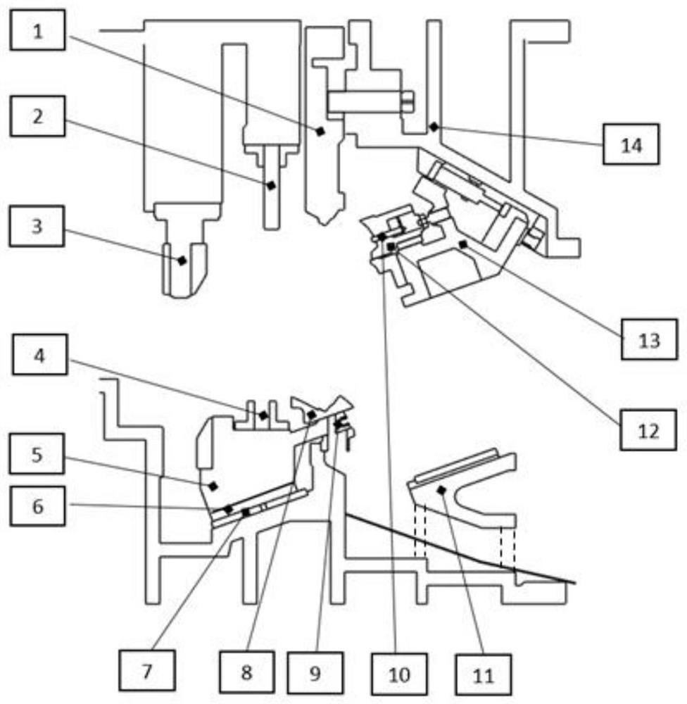
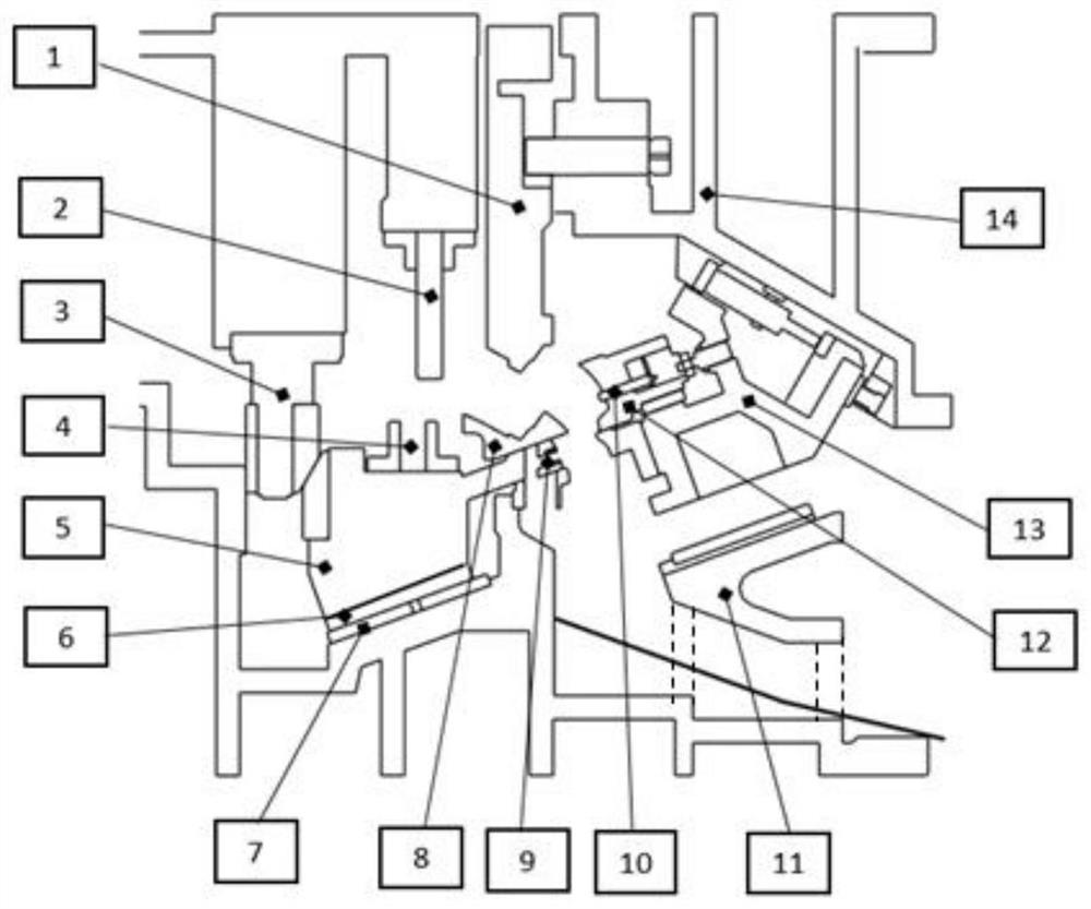
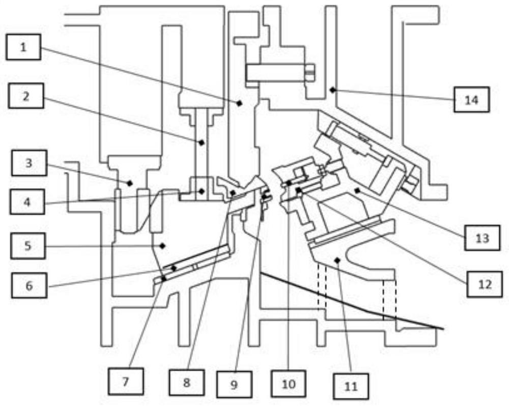
[0033] Such as Figure 1-Figure 4 As shown, the present embodiment provides a punching tool, including an upper base 14, a base 15, a first guide structure, a punch 5, a die sleeve 9 and a punch 10 arranged on the upper base 14, wherein: the base 15 is provided with a guiding inclined surface, and the punch 5 is slidingly matched with the guiding inclined surface. Due to the existence of the guiding inclined surface, when the punch 5 moves to the set direction, it is affected by its own gravity component to ensure the smooth and accurate movement of the punch 5. . The die set 9 is set on the punch 5, and the die set 9 is matched with the punch 10, the die set 9 is set on the base 15 along with the punch 5, and the movement of the punch 5 can avoid interfering with the removal of parts. It can realize the punching in the stamping process. The first guide structure includes a matching guide post 2 and a guide sleeve 4, one of which is set on the upper base 14, and the other is...

Embodiment 2

[0049] Based on the same inventive concept, a stamping and punching method provided by the present invention is implemented based on the above-mentioned punching tooling, including the following steps:

[0050] Place the parts to be punched on the base 15. Specifically, the parts to be punched are placed on the cover plate 8 fixedly arranged on the base 15. Since the punch 5 is movable, it is possible to operate the punch when picking and placing the parts. 5, to avoid interference with the loading and unloading of parts.

[0051] Control the upper base 14 to move the first set distance along the stamping direction, so that the punch 5 moves to the first set position along the guide slope, and the guide post 2 and the guide sleeve 4 are docked; the punch 5 is on the upper base 14 and the guide slope Compared with the horizontal guidance in the prior art, the present invention ensures the operation accuracy of the punch 5 through the inclined surface, avoiding the positioning d...


PUM


Abstract

The invention discloses a punching tool and a stamping and punching method. The punching tool comprises an upper base body, a base, a first guide structure, a male die, a female die sleeve and a punch arranged on the upper base body, a guide inclined plane is arranged on the base, and the male die is in sliding fit with the guide inclined plane; the female die sleeve is arranged on the male die and matched with the punch; and the first guide structure comprises a guide column and a guide sleeve which are matched, one of the guide column and the guide sleeve is arranged on the upper base body, the other one is arranged on the male die, and after the upper base body moves by a set distance in the stamping direction, the male die moves along the guide inclined plane till the guide column is in butt joint with the guide sleeve in a sleeved mode. According to the punching tool and the stamping and punching method, part taking and placing can be prevented from being interfered, and punching in the punching process can be achieved; and meanwhile, the guide inclined plane and the first guide structure are additionally arranged, so that the operation precision of the male die is ensured, positioning deviation is avoided, and the precision and stability of punching on a movable part can be ensured.

Description

technical field [0001] The invention relates to the technical field of punching and punching, in particular to a punching tool and a punching method. Background technique [0002] In the stamping process, there are cases of negative angle punching. In order to ensure that there is no interference with the punching structure of the lower die during the stamping production, the hole can only be made before the shape of the side wall of the part is formed in the traditional stamping process. Punch out before doing negative sidewall shaping. However, when the scheme of punching and reshaping is adopted, the hole is relatively close to the shaping area, and the deformation of the sheet metal during shaping is large, which will cause deformation of the punched hole during the wedge shaping process, and the position and shape of the hole Neither can be guaranteed, affecting the installation accuracy. [0003] Therefore, in order to ensure the accuracy of punching, punching must f...

Claims


Application Information

Patent Timeline
Patent Type & Authority Applications(China)
IPC IPC(8): B21D28/32B21D28/34B21D35/00B21D37/12
CPCB21D28/32B21D28/34B21D37/12B21D35/001
Inventor 李立经魏龙童钱虎邹平朱平
Owner VOYAH AUTOMOBILE TECH CO LTD
Why Eureka
Try Eureka