Passive direct loaded disk spring tension compensator

A disc spring and compensator technology, applied in the direction of overhead lines, etc., to achieve the effect of flexible load reduction, convenient debugging, and good constant force output performance

Inactive Publication Date: 2004-11-17
毛新悦 +1
View PDF1 Cites 1 Cited by
  • Summary
  • Abstract
  • Description
  • Claims
  • Application Information

AI Technical Summary

Problems solved by technology

[0005] On September 28, 1999, I proposed an active constant force disc spring electrified railway catenary tension compensator to the Chinese Patent Office. The application number is 99114464.3 and the announcement number is CN1289904A. This patent adopts the structure of double slewing arms and double pull shafts. In principle, it is designed based on its novel quality, with compact structure and accurate calculation, but the disc spring group parallel to the slideway will affect the accuracy of the constant force under the action of gravity, and there is a gap between the pull rod and the main shaft. interference phenomenon

Method used


Image

  • Passive direct loaded disk spring tension compensator
  • Passive direct loaded disk spring tension compensator
  • Passive direct loaded disk spring tension compensator

Examples


Embodiment Construction

[0015] Embodiments of the present invention will be further described below in conjunction with the accompanying drawings.

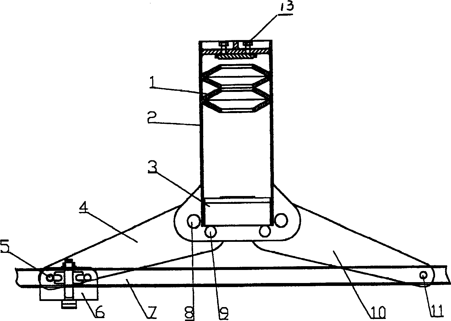
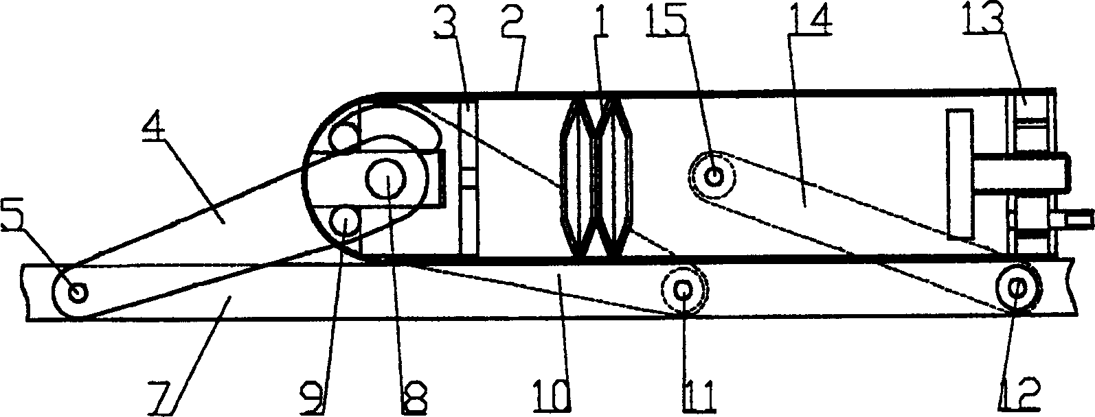
[0016] Depend on figure 1 It can be seen that, for the tension compensator with double-spindle structure, disc spring groups 1 are placed in pairs in the casing 2, and the front port of the casing 2 is provided with a pressure plate 3, and the shifting rotary arm 4 and the positioning rotary arm 10 are symmetrical through their independent spindles 8. The movable connection is on both sides of the center of the front port section of the shell 2, the final shaft 9 for positioning the rotary arm 10 and one end of the shifting rotary arm 4 is pressed on the pressure plate 3, the base 7 is strip metal, and the base 7 is provided with horizontal grooves and Through the vertical slot, the other end of the shifting rotary arm 4 slides in the horizontal slot through the ground load adjustment mechanism 6, and the other end of the positioning rotary arm 10 is fle...


PUM


Abstract

A directly loaded passive tension compensator for disk spring is composed of disk spring sets, a locating rotary arm, a shifting rotary arm and a load regualtor. A pair of disk spring sets is mounted in casing with press plate in its front end. Said two rotary arms are mounted to the casing in movable mode. Its rectangular metal base has horizontal and vertical slots. Its advantages are compact structure, high reliability, high utilization rate of disk spring, constant force output, and flexible load regulation.

Description

Technical field: [0001] The invention relates to a passive tension compensator, which is a single-coordinate, large-displacement compensation device, and is especially suitable for a constant force tension compensator of an electrified railway catenary. Background technique: [0002] The sag of the transmission cable of the electrified railway catenary changes due to the change of temperature. In order to eliminate this effect, it must be compensated by constant tension. [0003] At present, the passive constant force tension compensator used on electrified railways is composed of two fixed pulleys and a set of cement counterweights. Although this kind of compensator has a simple structure and can also achieve tension compensation, its performance is relatively poor, especially It is at the beginning of static and dynamic changes that the bending and straightening of the displacement of the wire rope on the pulley will absorb a lot of energy, which cannot meet the higher req...

Claims


Application Information

Patent Timeline
Patent Type & Authority Patents(China)
IPC IPC(8): B60M1/26
Inventor 毛新悦毛学军樊红
Owner 毛新悦
Why Eureka
Try Eureka