
Method of reducing interference, and radio system
A wireless system, spread spectrum code technology, applied in transmission systems, digital transmission systems, code division multiplexing systems, etc. The effect of small distractions
Patent Information
- Authority / Receiving Office
- CN · China
- Current Assignee / Owner
- Publication Date
- 2006-01-18
- Estimated Expiration
- Not applicable · inactive patent
Smart Images
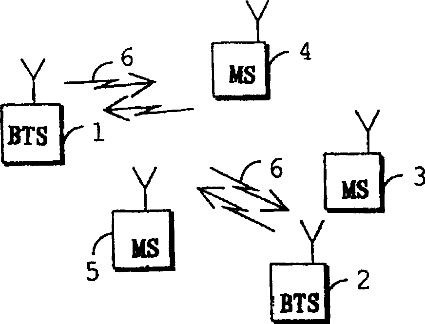
Figure 1 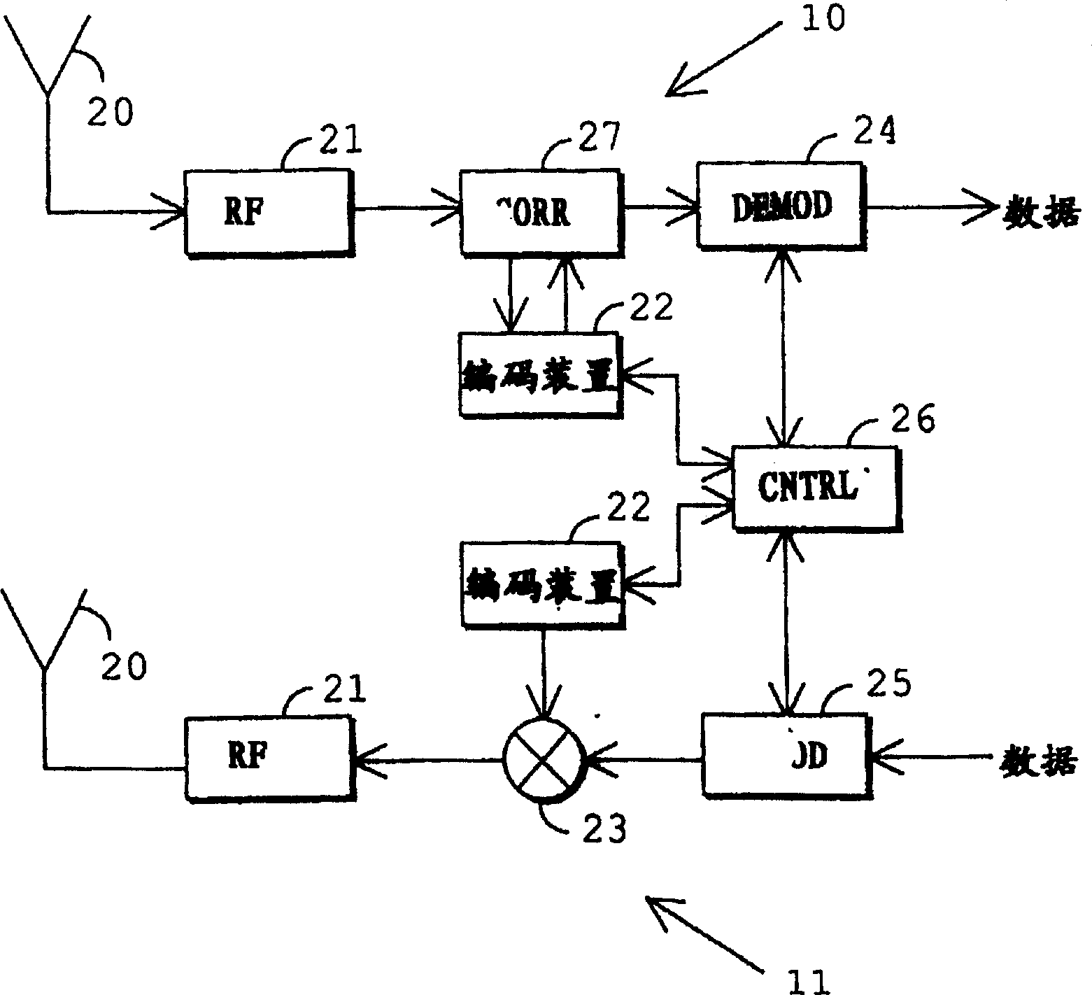
Figure 2 
Figure 3
Abstract
Description
technical field
[0001] The present invention relates to a method for reducing interference in a wireless system and a wireless system. Background technique
[0002] In CDMA (Code Division Multiple Access), a user's narrowband signal is multiplied by a spreading code and spread over a much wider frequency band. Multiple users transmit on the same frequency band simultaneously. On each connection between the base station and the user terminal, a different spreading code is used, and the signals of the users are differentiated in the receiver based on the spreading code of each user. Appropriate spreading codes are chosen such that their correlation with each other is as small as possible. Ideally, the signal multiplied by another spreading code would not correlate, would not revert to narrowband, and would appear as noise.
[0003] However, in conventional CDMA, the cross-correlation between different spreading codes is generally too high, because the time lengths and usual...
Examples
Embodiment Construction
[0021] The invention can be applied to any wireless system using spreading codes, such as a CDMA system.
[0022] figure 1 A typical CDMA wireless system is shown. The radio system comprises a plurality of cells, each cell generally comprising a base station 1 and 2, and a plurality of user terminals 3 to 5, preferably mobile telephones. Both the base stations 1 and 2 and the user terminals 3 and 5 comprise at least one transceiver, via which a connection 6 between the user terminals 3 to 5 and the base stations 1 and 2 is established and maintained. The subscriber terminals 3 to 5 are preferably mobile telephones, and during the connection 6 they and the base stations 1 and 2 transmit spread spectrum coded signals to each other.
[0023] figure 2 A block diagram of a typical transceiver is shown. The transceiver comprises antenna 20 , radio frequency means 21 , transmitter multiplier 23 , encoding means 22 , demodulator 24 , modulator 25 , control means 26 and receiver m...