

Device and method for determining hydraulic unit output speed in hydraulic mechanical gearing means
A hydraulic unit and transmission technology, applied in transmission, transmission control, fluid transmission, etc., can solve the problems of low output speed, low speed pulse frequency, expensive directional Hall effect sensor and magnetic ring, etc.
- Summary
- Abstract
- Description
- Claims
- Application Information
AI Technical Summary
Problems solved by technology
Method used
Image

Examples
Embodiment Construction
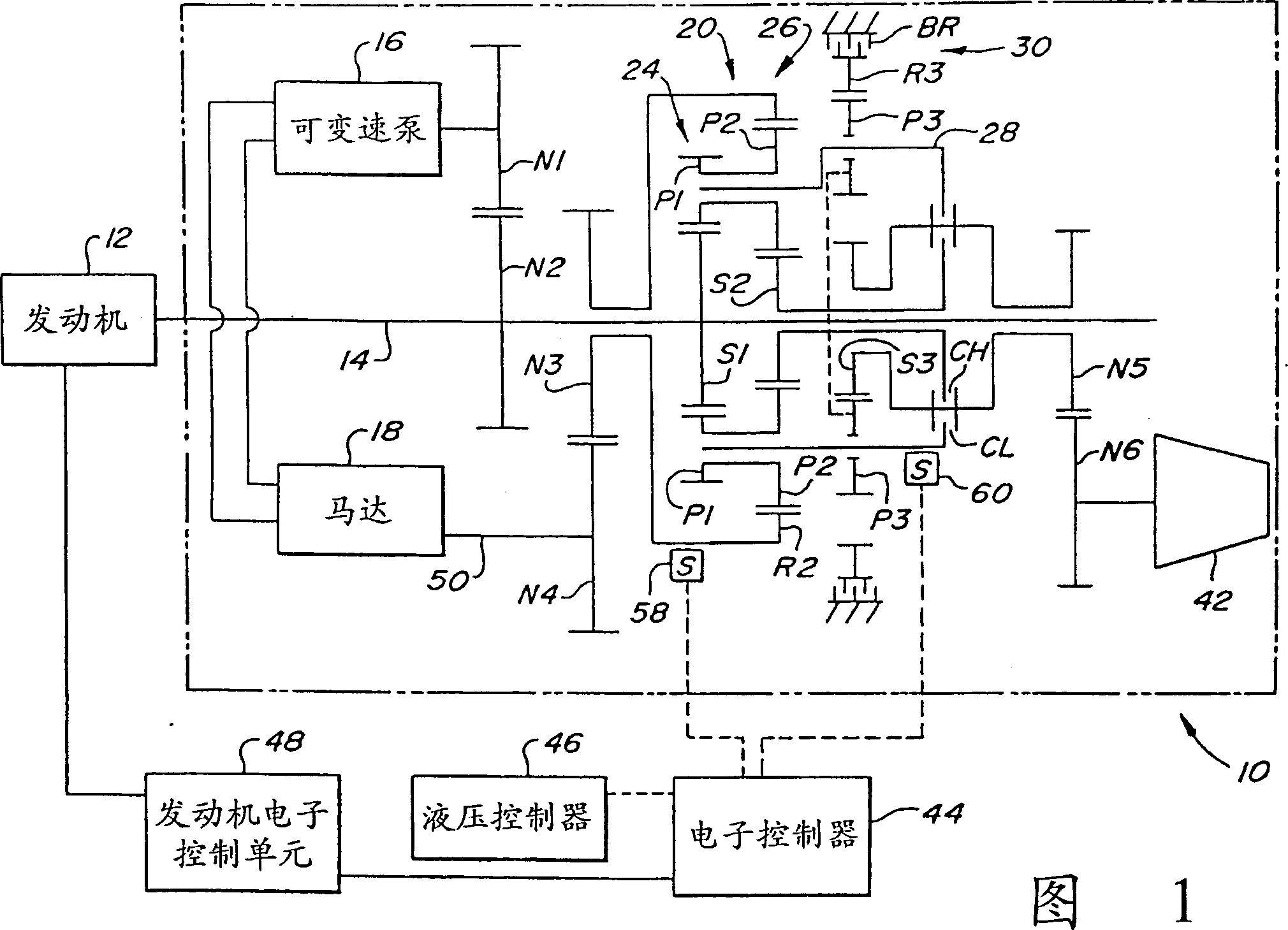
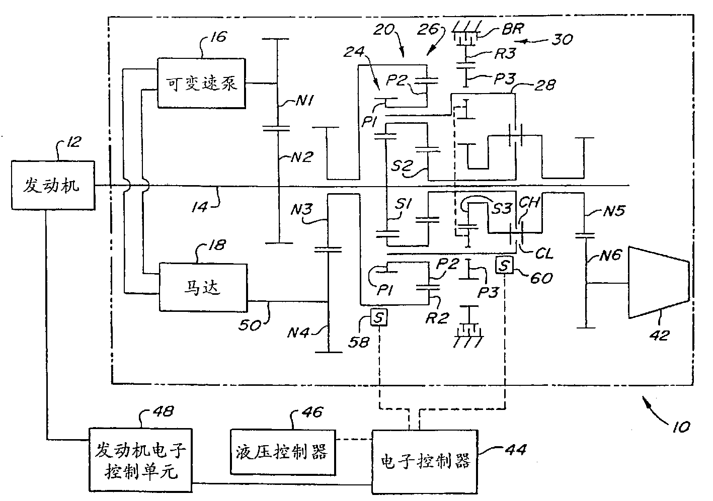
[0012] The hydromechanical transmission according to the invention is shown in FIG. 1 and indicated by reference 10 . The transmission 10 is adapted to be driven by an engine 12 having an output shaft 14 . The transmission further comprises a hydraulic unit comprising a variable speed pump 16 and a motor 18 driven by the pump 16 . The output shaft 14 of the engine drives a hydraulic pump 16 through gears N2 and N1.
[0013] The transmission includes a planetary gear system 20 having first and second planetary gear sets 24 and 26 . The planetary gear sets have a common planetary gear carrier 28 on which are mounted integral planetary gears P1 and P2 respectively of the two planetary gear sets. A separate ring gear R2 is used to mesh with the planetary gears P2. The engine output shaft 14 also drives the sun gear S1 of the first planetary gear set 24 at the same time. The second planetary gear set 26 has a sun gear S2.
[0014] The transmission has two clutches, a low range...
PUM
 Abstract
Description
Claims
Application Information