

Door hinge with concealed bearing
A hinge device and hidden technology, which is applied in door/window accessories, wing leaf parts, hinge boards, etc., can solve the problems of severe wear of hinge devices, high wear of bearing devices, and inconvenience for people
- Summary
- Abstract
- Description
- Claims
- Application Information
AI Technical Summary
Problems solved by technology
Method used
Image

Examples
Embodiment Construction
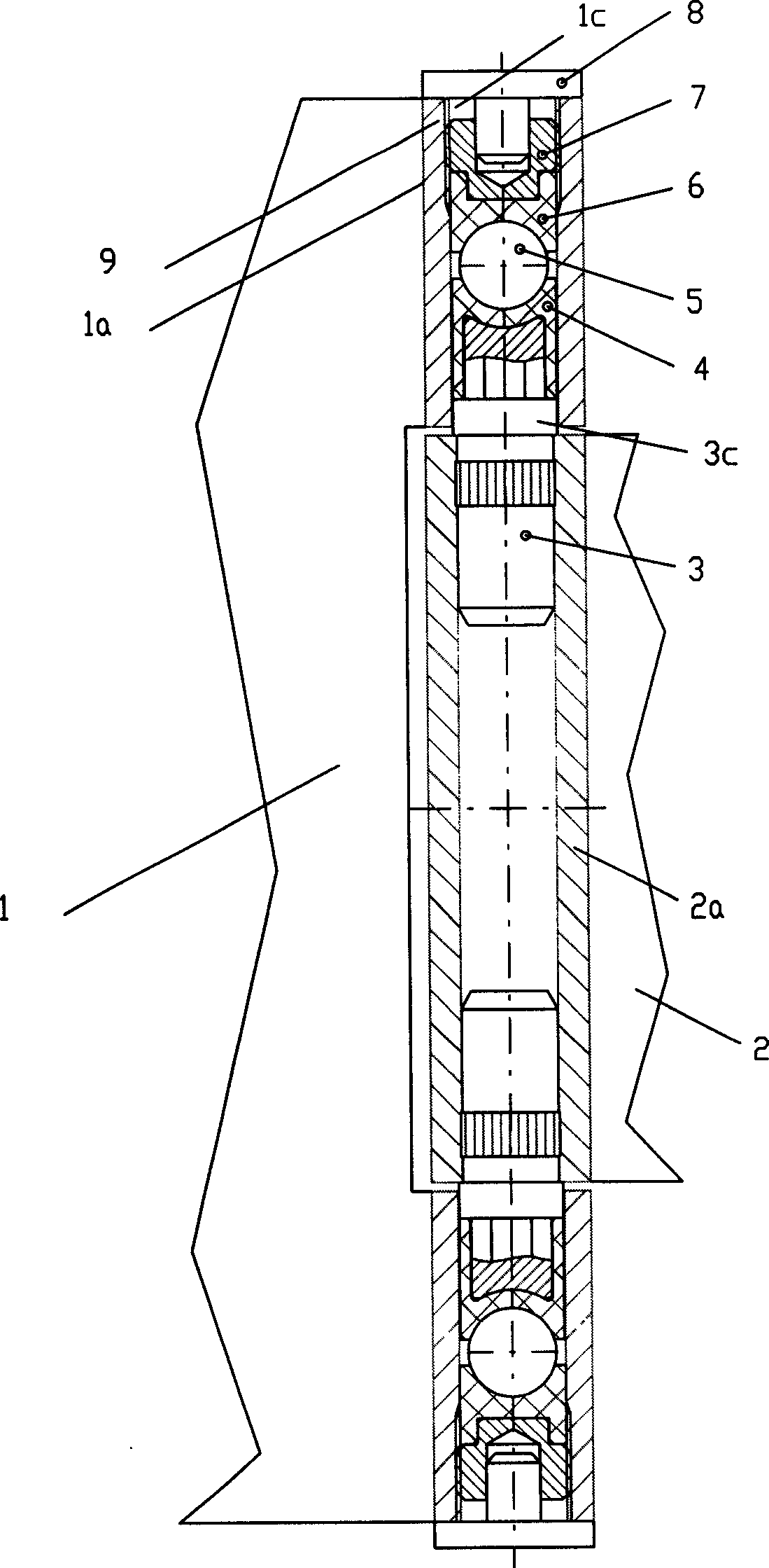
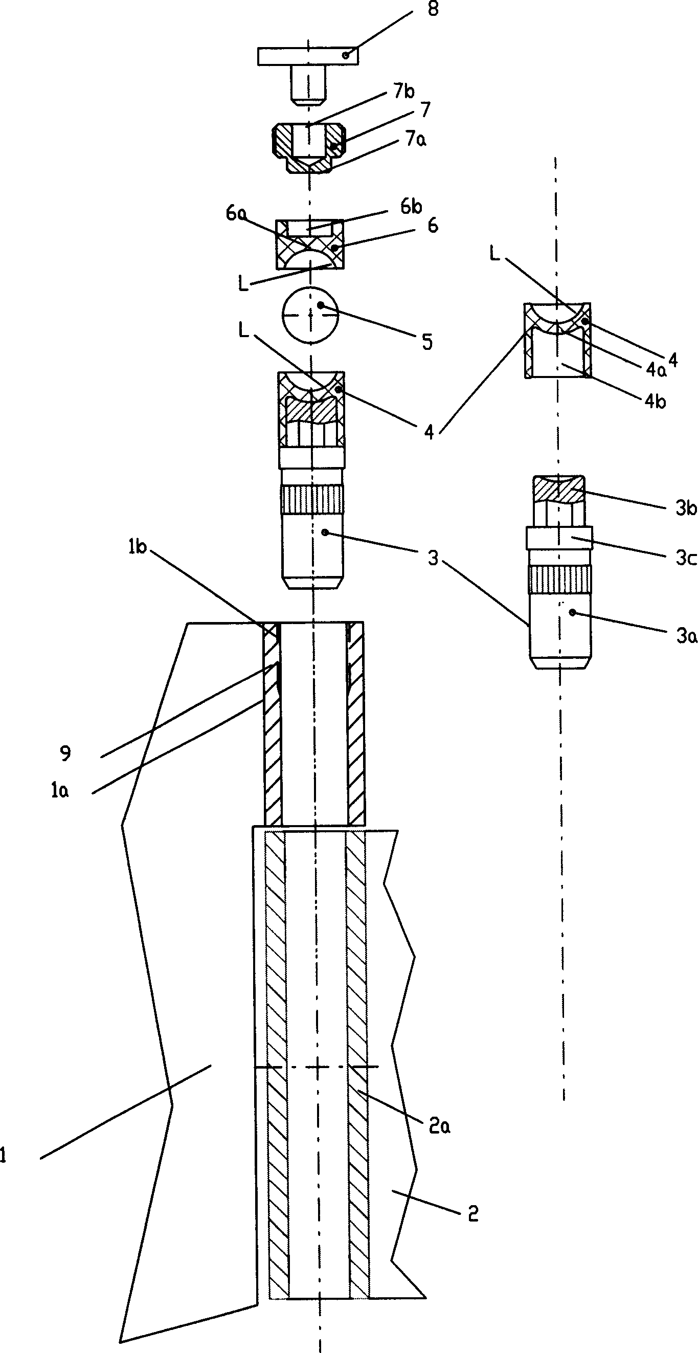
[0012] A door hinge device consisting of an inner and outer door hinge unit including additional means to allow it to be mounted to a door frame or door; the inner door hinge unit is mounted on the Between two or more cylindrical bearing parts on the external door hinge unit; inside the bearing parts there are first bearing sleeve and second bearing sleeve are set, the bearing sleeve is made of special engineering material plastic steel POM PTFE It is made; there is a ball between the first bearing sleeve and the second bearing sleeve, the ball is made of metal material, the door hinge device also includes a supporting bolt and an adjusting screw, and the first bearing sleeve is close to the inner The direction of the door hinge unit is firmly sleeved on the free end of the support bolt; the adjustment screw can be screwed into the bearing part; the second bearing sleeve is subjected to the counter pressure of the ball, away from the first bearing sleeve.
[0013] The door hin...
PUM
 Abstract
Description
Claims
Application Information