Thread processing system and method for controlling and /or monitoring the system

A technology of processing system and yarn, applied in the direction of program control, computer control, general control system, etc., to achieve the effect of simple wiring

Inactive Publication Date: 2011-03-30
IROPA AG (CH)
View PDF5 Cites 1 Cited by
  • Summary
  • Abstract
  • Description
  • Claims
  • Application Information

AI Technical Summary

Problems solved by technology

The program is expensive and complex

Method used


Image

  • Thread processing system and method for controlling and /or monitoring the system
  • Thread processing system and method for controlling and /or monitoring the system
  • Thread processing system and method for controlling and /or monitoring the system

Examples


Embodiment Construction

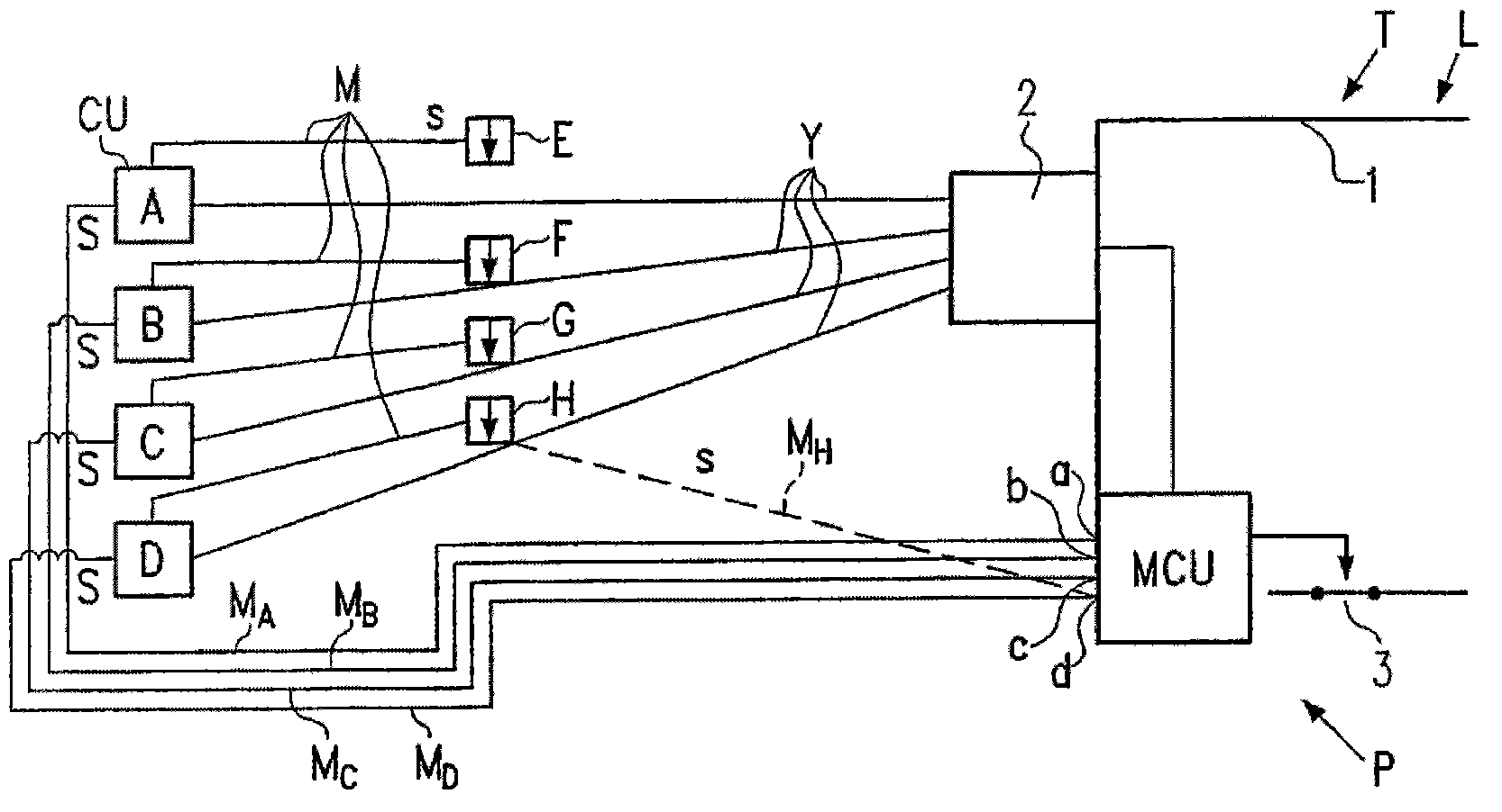
[0047] like figure 1 Shown in (Prior Art), the yarn processing system P comprises, for example, a loom L having a weaving shed 1 as a weaving machine T, a yarn selection device 2 connecting several yarn passages, an electronic controller MCU and a main switch3. The loom L pulls the weft yarn Y from the yarn input units A to D intermittently and in accordance with a pattern ratio. In each yarn channel, additional accessory devices E to H (signal transmitters not shown) can be connected to the yarn input unit, like a yarn breakage monitor or a weft yarn monitor. In the place of the yarn input unit, which is only symbolically marked with its electronic control unit CU, further internal or peripheral signal transmitters can be placed such as temperature sensors, yarn break sensors, voltage sensors and Analogues are replaced, so that for each yarn input channel provided with several signal transmitters in some examples, each transmitter can generate an alarm signal and / or a stat...


PUM


Abstract

The invention relates to a thread processing system (P) comprising textile machinery and several thread delivery devices (A - D), electronic controllers (CU, MCU) at least for controlling the textile machinery and thread delivery devices, alarm and / or status signal generators that emit anonymous signals (S) and are located in the devices or on their periphery and a single signal line (Mn), to which signal generators are attached and which leads to the controller (MCU) of the textile machinery. According to the invention, the signal line (Mn) extends between a coding station on the side of thedevices and a decoding station on the side of the textile machinery controller (MCU), each signal can be modulated in its length in accordance with the thread channel of the signal generator and at least the thread channel of the signal generator can be taken into consideration by means of the decoding station in the textile machinery controller, in addition to the signal obtained from the individually modulated signal length. Each signal is individually coded prior to its transmission via the signal line by modulating the signal length and is identified in the textile machinery controller using the signal generator coding or the thread channel thereof.

Description

technical field [0001] The invention relates to a yarn handling system and a method of controlling and / or monitoring the system. Background technique [0002] During the operation of a yarn handling system (e.g. a loom and several weft yarn inputs or a knitting machine and several knitting yarn inputs), warning or status signals can be placed in the yarn input device or in ancillary equipment / generated everywhere. Warning or status signals originate from signal transmitters at the respective locations and must be transmitted to the textile machine controller without delay. Causes of such a signal are, for example, a broken yarn, wrong supply voltage, overheating conditions, mechanical faults, or similar faults. Textile machine controllers are designed to respond differently to this signal. Textile machines, for example, can be switched off. In the case of several yarn input units inputting yarn of the same quality, the textile machine by ignoring the affected yarn chan...

Claims


Application Information

Patent Timeline
Patent Type & Authority Patents(China)
IPC IPC(8): D03D47/34D04B15/48G05B19/042D04B35/12D04B35/14
CPCD03D47/34D04B35/14G05B2219/45193D04B35/12D04B15/48
Inventor 托马斯·伦德贝里帕·约瑟夫松
Owner IROPA AG (CH)
Why Eureka
Try Eureka