Light focusing device for multi-head lamp

A technology of concentrating devices and multi-head lamps, which is applied in the direction of lighting devices, lighting auxiliary devices, lighting device components, etc., and can solve problems such as low bulb life, large reflectors, and difficult mold processing

Inactive Publication Date: 2006-10-04
沙利锡
View PDF0 Cites 21 Cited by
  • Summary
  • Abstract
  • Description
  • Claims
  • Application Information

AI Technical Summary

Problems solved by technology

This kind of surgical lamp has low luminous efficiency and high energy consumption; the infrared is strong, the color filter glass has a large loss of useful light, the temperature of the lampshade and the light spot rises, the material requirements are high, the reliability is poor, and the life of the bulb is low; the reflector is large, and the mold processing Difficult, big investment

Method used


Image

  • Light focusing device for multi-head lamp
  • Light focusing device for multi-head lamp
  • Light focusing device for multi-head lamp

Examples


Embodiment Construction

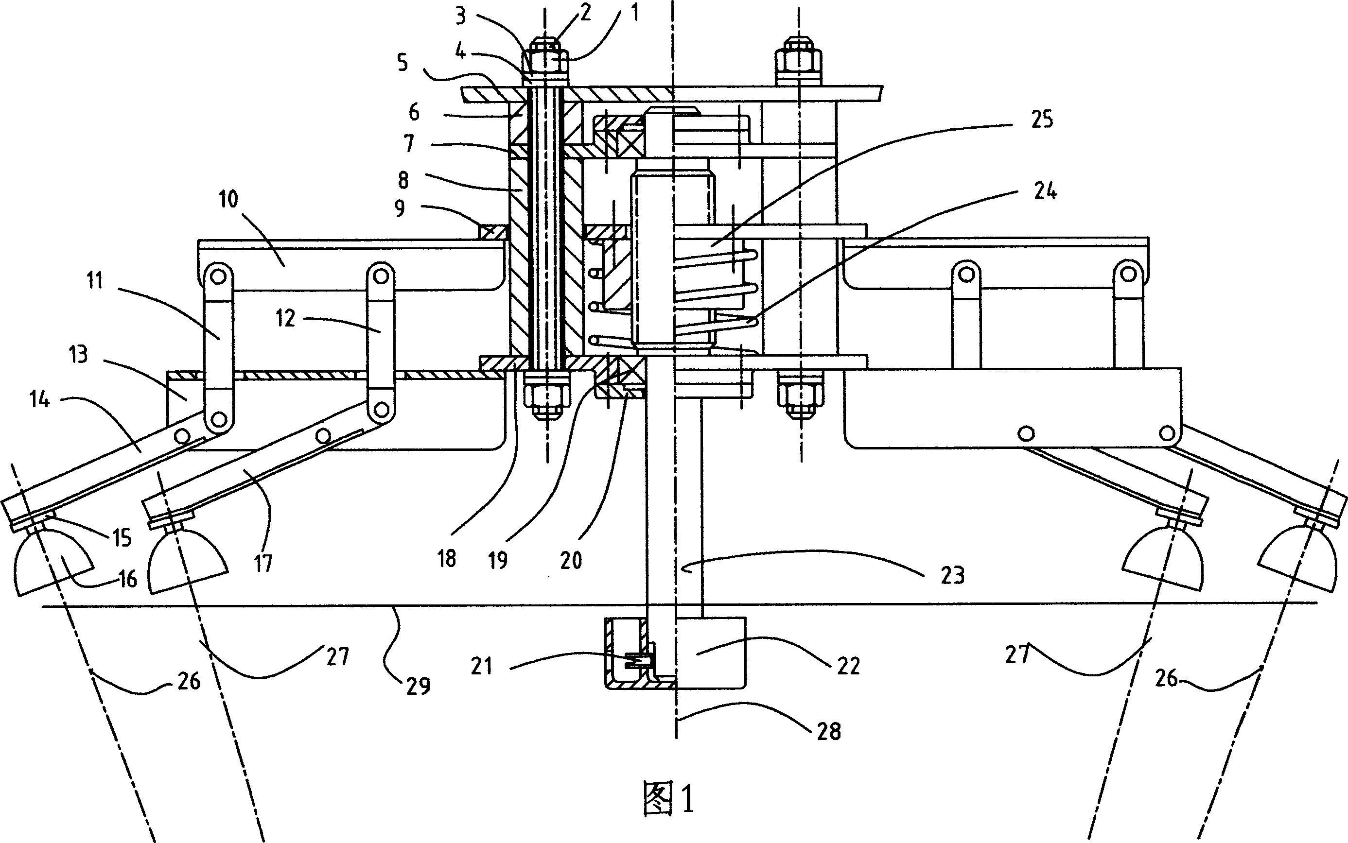
[0016] Fig. 1 is an embodiment: inside and outside lever part 17 and part 14 Figure 8 Angle A in the middle, make the lamp in the middle position of reciprocating movement, the central axis 26,27 of the light of each lamp 16 in the multi-head lamp intersects on the central axis 28 of the light-collecting device, and the distance required by the products outside the panel 29 (such as 1m ) place. The nut 25 and the screw rod 23 are threadedly connected, and the rotation of the screw rod 23 is used to move the nut 25, change the distance between the connecting rod bracket and the lever bracket, and change the distance between the central axis 26, 27 of each light in the multi-head lamp and the central axis 28 of the focusing device. to change the spotlight position.

[0017] The lever bracket 13 is fixed on the lever bracket mounting plate 18, and the lever bracket mounting plate 18 is fixed on the multi-head lamp lamp frame or the On the outer cover 5 of the multi-head lamp; ...


PUM


Abstract

The invention discloses a multiple-head lamp focusing device for surgery operation luminous device, which comprises the following parts: connecting rack, lever rack, connecting rod and lever, wherein the distance between two racks and lightness can be adjusted along with the separation angle of light axle and focusing device axle, which focuses the light on the axle center; the multiple-head lamp can be assembled on multiple circumstances at the same axle; one connecting rack and lever rack load one or more connecting rods and levers.

Description

technical field [0001] It is a multi-head lamp concentrating device, which can be used as a shadowless lamp concentrating device for surgery. Background technique [0002] Surgical shadowless lamps use incandescent lamps, use reflectors to reflect the light emitted by incandescent lamps to the outside of the lamp, and adjust the distance between the brightest spot of the shadowless lamp and the shadowless lamp panel by adjusting the position of the incandescent lamp on the central axis in the reflector . This kind of surgical lamp has low luminous efficiency and high energy consumption; the infrared is strong, the color filter glass has a large loss of useful light, the temperature of the lampshade and the light spot rises, the material requirements are high, the reliability is poor, and the life of the bulb is low; the reflector is large, and the mold processing Difficult, big investment. Contents of the invention [0003] These deficiencies can be avoided by using ligh...

Claims


Application Information

Patent Timeline
Patent Type & Authority Applications(China)
IPC IPC(8): F21V14/02F21V19/02F21V21/14F21W131/205F21Y113/00
Inventor 沙利锡沙利球
Owner 沙利锡
Why Eureka
Try Eureka