

Phase-switching dual-mode frequency divider and frequency synthesizer including the frequency divider
A phase switching, dual-mode frequency divider technology, applied in pulse counters, automatic power control, counting chain pulse counters, etc., to achieve the effect of saving chip area and high speed
- Summary
- Abstract
- Description
- Claims
- Application Information
AI Technical Summary
Problems solved by technology
Method used
Image

Examples
Embodiment Construction
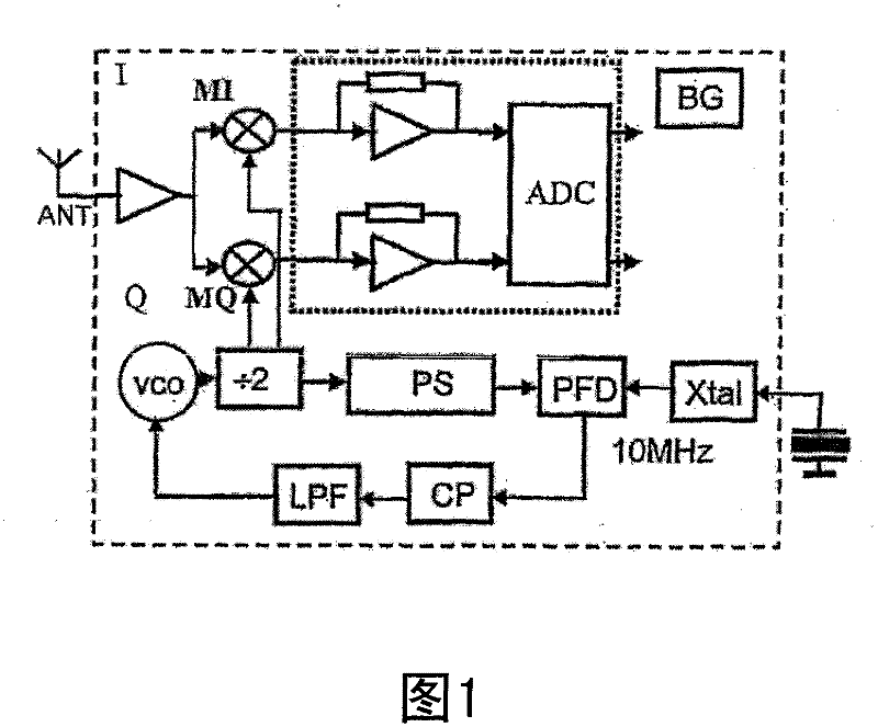
[0032] figure 1 A block diagram showing a receiver that can be used for the IEEE 802.11a standard. figure 1 The upper part of , shows the antenna ANT connected to the low noise amplifier LNA, which is connected to the first and second mixers MI, MQ, which in turn are connected to the analog-to-digital converter ADC. figure 1 The lower part shows the implementation of the PLL circuit. The PLL circuit includes a voltage oscillator VCO, a first divide-by-2 circuit, a frequency divider PS, a phase frequency detector PFD, a reference crystal Xtal, a charge pump CP and a low-pass filter LPF. The output of the divide-by-2 circuit is coupled to first and second mixers MI, MQ.
[0033] The frequency divider PS will be described in more detail below.
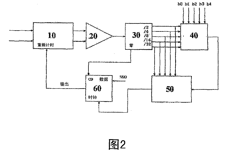
[0034] figure 2 show figure 1 Block diagram of the frequency divider in . The programmable frequency divider includes a 16 / 17 frequency divider 10, a buffer 20, a frequency divider 30, a decision unit 40, a synchronization unit...
PUM
 Abstract
Description
Claims
Application Information