Switch device

A switch device and switching technology, which is applied in the direction of lighting devices, lamp circuit layout, light source, etc., can solve the problems of difficult light source lighting, no specific means of light source lighting, etc., and achieve the effect of simple structure

Inactive Publication Date: 2007-04-25
FUJI IND
View PDF1 Cites 0 Cited by
  • Summary
  • Abstract
  • Description
  • Claims
  • Application Information

AI Technical Summary

Problems solved by technology

[0004] In the above-mentioned conventional switch device, although the light source is turned on when the button knob of the switch is pressed to operate the switch, in this conventional switch device, there is no specific me...

Method used


Image

  • Switch device
  • Switch device
  • Switch device

Examples


Embodiment Construction

[0029] A first embodiment of the switchgear of the present invention will be described.

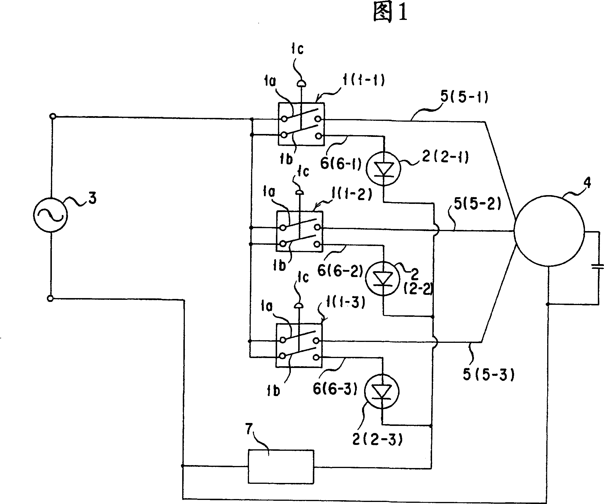
[0030] As shown in FIG. 1 , a switch device is formed by a switch 1 and a light source 2 .

[0031] The switch 1 described above includes a main switch unit 1a, an auxiliary switch unit 1b, and an operation unit 1c for simultaneously connecting and disconnecting the main switch unit 1a and the auxiliary switch unit 1b.

[0032] The said main switch part 1a is provided in the main circuit 5 which connects the power supply 3 and the electric equipment 4, and connects and disconnects this main circuit 5.

[0033] The electric device 4 is energized when the main switch unit 1a is connected, and is not energized when disconnected.

[0034] The auxiliary switch unit 1 b is provided in an auxiliary circuit 6 connecting the power source 3 and the light source 2 , and connects and disconnects the auxiliary circuit 6 .

[0035] The light source 2 is energized when the auxiliary switch part 1b is ...


PUM


Abstract

Provided is a switching arrangement having a simple structure, wherein it can be confirmed by viewing that a switch is in an operating state if a light source is lighted. This switching arrangement is structured so that a switch 1 is equipped with a main switch part 1a, an auxiliary switch part 1b, and an operating part 1c, wherein the main switch part 1a and the auxiliary switch part 1b are brought into a connected state by operating the operating part 1c, a motor operated apparatus 4 is switched on if the main switch part 1a is connected, a light source 2 is lighted if the auxiliary switch 1b is connected, and if the light source 2 is lighted, it can be confirmed that the switch 1 is in the operating state. Since it is sufficient if the operating state of the switch can be confirmed by viewing the light source 2, and the switch 1 is equipped with the main switch part 1a, and the auxiliary switch part 1b, the structure of the switching arrangement is simple.

Description

technical field [0001] The present invention relates to a switch device that includes a switch and a light source, and enables visual confirmation that the switch is in an operating state by turning on the light source. Background technique [0002] Conventionally, various switch devices including a switch and a light source have been proposed, and by turning on the light source, it is possible to visually confirm that the switch is in an actuated state. [0003] For example, as disclosed in Japanese Patent Application Laid-Open No. 2003-100166, the following switch device is known: a light source is provided opposite to the button knob of the switch, and if the button knob is pressed to operate the switch, the light source lights up and illuminates the button knob, It is possible to confirm that the switch is operating by visually viewing the button knob. [0004] In the above-mentioned conventional switch device, although the light source is turned on when the button knob...

Claims


Application Information

Patent Timeline
IPC IPC(8): H05B37/02
Inventor 大矢秀和
Owner FUJI IND
Why Eureka
Try Eureka