Method for implementing virtual router redundancy protocol switching between primary/standby devices

A redundant protocol and backup equipment technology, applied in the field of network communication, can solve problems such as interruption of uplink business, failure to establish LSP, failure of IGP/BGP route convergence, etc., to achieve the effect of shortening time and avoiding interruption of uplink business

A redundant protocol and backup equipment technology, applied in the field of network communication, can solve problems such as interruption of uplink business, failure to establish LSP, failure of IGP/BGP route convergence, etc., to achieve the effect of shortening time and avoiding interruption of uplink business

CN1968260AActive Publication Date: 2007-05-23HUAWEI TECH CO LTD

Image

  • Method for implementing virtual router redundancy protocol switching between primary/standby devices
  • Method for implementing virtual router redundancy protocol switching between primary/standby devices

Examples


Embodiment Construction

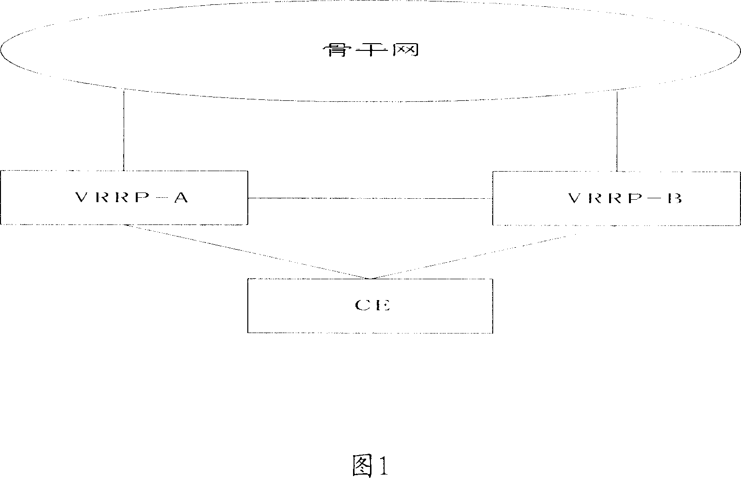
[0049] The present invention provides a method for realizing VRRP switchover between primary and backup devices. The core of the present invention is: each VRRP device monitors the state of its uplink interface and specified route, as well as its uplink According to the status of various designated IGP and other protocols, adjust the priority of the VRRP device according to the monitoring results.

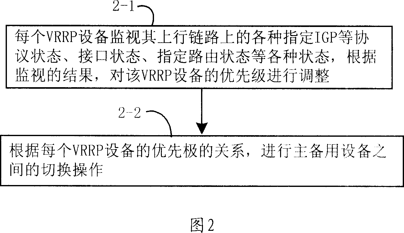
[0050] Describe the method of the present invention in detail below in conjunction with accompanying drawing, the specific processing flow of the method of the present invention is as shown in Figure 2, comprises the following steps:

[0051] Step 2-1. Each VRRP device monitors various statuses such as various designated IGP protocol states, interface states, and designated route states on its uplink, and adjusts the priority of the VRRP device according to the monitoring results.

[0052] In the present invention, each VRRP device monitors the states of protocols such as various d...


PUM


Abstract

The invention relates to a method for realizing VRRP (virtual route abundant protocol) switch between main and backup devices, wherein said method comprises that: each VRRP device detects the state of all appointed protocols of ascending chain; the VRRP device via the detecting result adjusts priority; via the priority relation of VRRP devices, switch VRRP between main and backup devices. The invention can select switch time accurately, and avoid service interruption.

Description

technical field [0001] The invention relates to the field of network communication, in particular to a method for realizing VRRP (Virtual Router Redundancy Protocol, Virtual Router Redundancy Protocol) switching between primary and backup devices. Background technique [0002] With the development of network technology, users have increasingly higher requirements for network reliability. User equipment usually requires access to dual gateways, and VRRP runs between the two gateways. VRRP can make the switching of gateway equipment transparent to user equipment. Figure 1 shows a typical VRRP network. In a VRRP network, which device is the primary device and which device is the backup device is determined according to the priority configured on each device. [0003] Only the active device can receive the packets uploaded by the user equipment and forward the packets to the upper-layer network. When for some reason, the priority of the standby device is higher than that of the...

Claims


Application Information

Patent Timeline
23 May 2007
Publication
CN1968260A
IPC
H04L29/06; H04L12/56; H04L45/586
Inventors
熊怡