

High contrast electro-optic liquid crystal camera iris providing angle independent transmission for uniform gray shades
a liquid crystal camera and gray shade technology, applied in the field of liquid crystal iris, can solve the problems of unsatisfactory use as a camera iris, complex device, and inability to meet the requirements of many miniature camera applications, and achieve the effect of maximum light transmission, zero transmittance, and maximum throughpu
- Summary
- Abstract
- Description
- Claims
- Application Information
AI Technical Summary
Benefits of technology
Problems solved by technology
Method used
Image

Examples
first embodiment
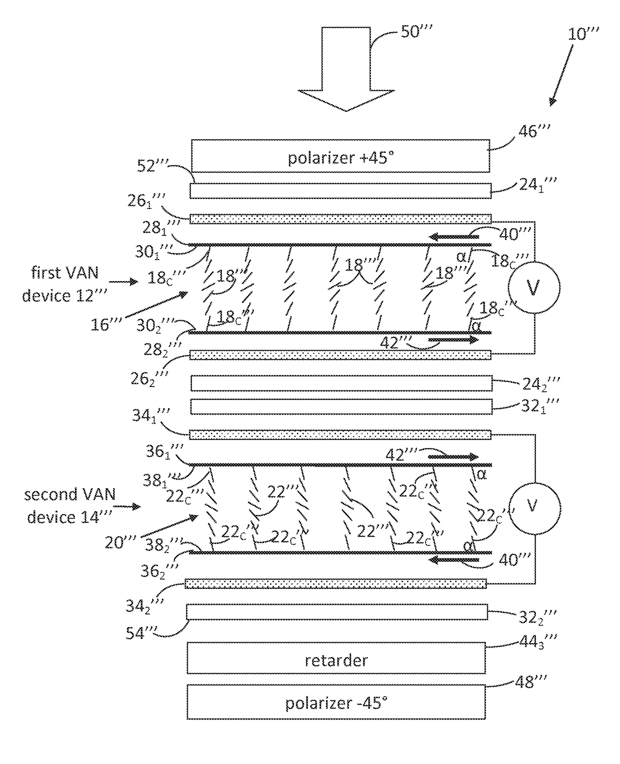
[0041]FIG. 5 is a simplified diagram of a liquid crystal iris 10 configured as a first implementation of the disclosed electro-optic liquid crystal camera iris. Liquid crystal iris 10 comprises a first ECB liquid crystal device 12 and a second ECB liquid crystal device 14, each of which contains liquid crystal having a positive dielectric anisotropy. For simplicity, index matching coatings of each of ECB liquid crystal devices 12 and 14 are omitted from the diagram. ECB liquid crystal devices 12 and 14 have, respectively, a director field 16 composed of liquid crystal directors 18 and a director field 20 composed of liquid crystal directors 22. Each of director fields 16 and 20 is shown in FIG. 5 at an intermediate drive voltage, V. Director field 20 of ECB liquid crystal device 14 is a mirror image of director field 16 of ECB liquid crystal device 12. In other words, liquid crystal directors 22 in director field 20 are reversely arranged in comparison to corresponding liquid crysta...
second embodiment
[0068]FIG. 21 shows the viewing angle dependence of the normalized transmitted luminance under application of a drive voltage of 2.61V, which produces 50% normalized transmitted luminance at normal incidence. These data are presented in FIG. 21 in the form of a normalized iso-transmitted luminance polar contour diagram. Comparing FIG. 21 with FIG. 2 for the prior art TN iris, it is apparent that there is remarkably less angular variation in transmitted luminance. The liquid crystal iris of the second embodiment is eminently suitable for use as a camera iris because it can achieve a high contrast ratio and exhibits capability to maintain a uniform gray level over a wide range of light input angles.
[0069]FIG. 22 shows a simulated transmitted luminance electro-optic curve of an example of a third embodiment of the disclosed electro-optic liquid crystal camera iris. The construction of the third embodiment is the same as that of liquid crystal iris 10 shown in FIG. 5, except as describe...
third embodiment
[0070]FIG. 23 shows the viewing angle dependence of the normalized transmitted luminance under application of a drive voltage of 2.69V, which gives 50% transmitted luminance at normal incidence. These data are presented in FIG. 23 in the form of a normalized iso-transmitted luminance polar contour diagram. Comparing FIG. 23 with FIG. 2 for the prior art TN iris, it is apparent that there is remarkably improved uniformity of the angular dependence of the 50% gray level. The liquid crystal iris device of the third embodiment is eminently suitable for use as a camera iris because it can achieve a high contrast ratio and exhibits capability to maintain a uniform gray level over a wide range of light input angles.
[0071]FIG. 24 is a block diagram of an example of a camera module 60 that includes the liquid crystal iris of any of the three embodiments of the disclosed electro-optic liquid crystal camera iris. FIG. 24 shows liquid crystal iris 10 of the first embodiment for purposes of conv...
PUM
| Property | Measurement | Unit |
|---|---|---|
| drive voltage | aaaaa | aaaaa |
| polar angle | aaaaa | aaaaa |
| azimuthal angle | aaaaa | aaaaa |
Abstract
Description
Claims
Application Information