Headwear accessory mounting clip and system

a technology for accessories and mounting clips, applied in the field of accessories, can solve the problems of many users eschewing elastic band mounts, unsatisfactory type mounts, and many deficiencies of users

Active Publication Date: 2018-10-23
VOLMER ENTERPRISES INC
View PDF25 Cites 6 Cited by
  • Summary
  • Abstract
  • Description
  • Claims
  • Application Information

AI Technical Summary

Benefits of technology

[0009]The preferred embodiment clip overcomes the deficits of the prior art and allows for the secure mounting of accessory devices on a hat brim. The device works particularly well when used to mount accessories on the brim (a / k / a bill) of a baseball cap. Such a brim typically has a front edge that has an edge (“front-to-back”) curvature of certain radius. The brim also has a thickness. The brim also has a transverse curvature (also known as a “bend”) of a certain radius. The preferred embodiment clip adapted for attachment to such a brim comprises a first (top) panel and a second (bottom) panel. The first and second panels respectively have a length, a width, a top surface, a bottom surface, a proximal end and a distal end.
[0011]Importantly and in contra-distinction to the prior art, the second panel has a wedge-shaped portion in which the width of the panel increases from the distal end of the panel to the proximal end of the panel. This allows the bottom of the clip to cut into and frictionally engage the bottom of the hat brim due to the transverse radius of the hat brim. This frictional engagement increases the purchase of the clip against the hat brim.
[0012]Also adding to the friction-creating contact between the preferred embodiment clip and hat brim is the fact that the clip has a plurality of convex and concave surfaces. For example, in the preferred embodiment, the bottom (inner) surface of the first panel is concave. This concavity has a radius closely equal to that of the transverse curvature of the brim. This allows for increased surface contact with the top of the hat brim and hence an increased frictional hold. A second friction augmenting feature is the shape of the second panel. In this respect, the top surface of the second panel is convex. The convexity has a radius closely equal to that of the transverse curvature of the brim. A third friction augmenting feature is built into the nose segment, which in the preferred embodiment has a plurality of concave surfaces that can mirror both the edge curvature and transverse curvature of the typical baseball cap. For example, in the preferred embodiment, the intermediate brim-facing surface of the nose segment is concave and the concavity closely approximates that of the edge curvature of the hat brim. Additionally, at the distal end of the second panel, the top surface of the second panel includes a channel. This channel too can have a convex floor and sidewall. This channel serves to gather the stitched border of fabric that is found on the undersurface of the brim about the brim's perimeter. By receiving this fabric, the brim-holding ability of the clip is enhanced.

Problems solved by technology

Many users eschew the elastic band mounts because of a variety of reasons, including vanity and discomfort.
They all, however, suffer from a wide array of deficiencies.
This type mount is undesirable because it physically deforms the subject cap in permanent fashion.
Also, the hole through which the post is pierced can loosen with time, causing the mount to undesirably shake and wobble.
Alligator clip mounts have several deficiencies which make their performance less than desirable for use with accessory devices.
In one instance, the alligator clip is bulky and its portion that is positioned underneath the bill will provide a visual distraction or obstruction.
Secondly, this type of clip focuses its gripping force and brim contacting surfaces at one end of the clip—the end not localized at the cap brim edge.
As a result, alligator clip type mounts do not provide sufficient grip to keep a heavier device like a POV camera in place when the user is involved in any type of vigorous activity.
The currently available versions do not work well with heavier devices like POV cameras.
In this respect the clips tend to slide across and off the cap bill because they: a) do not create enough clamping force with the bill; b) do not provide for sufficient frictional contact with the bill; or both.

Method used


Image

  • Headwear accessory mounting clip and system
  • Headwear accessory mounting clip and system
  • Headwear accessory mounting clip and system

Examples


Embodiment Construction

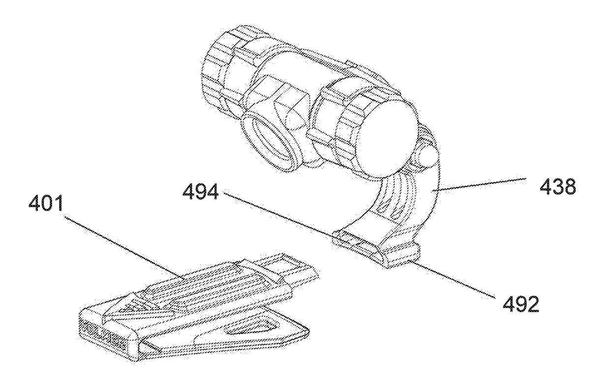
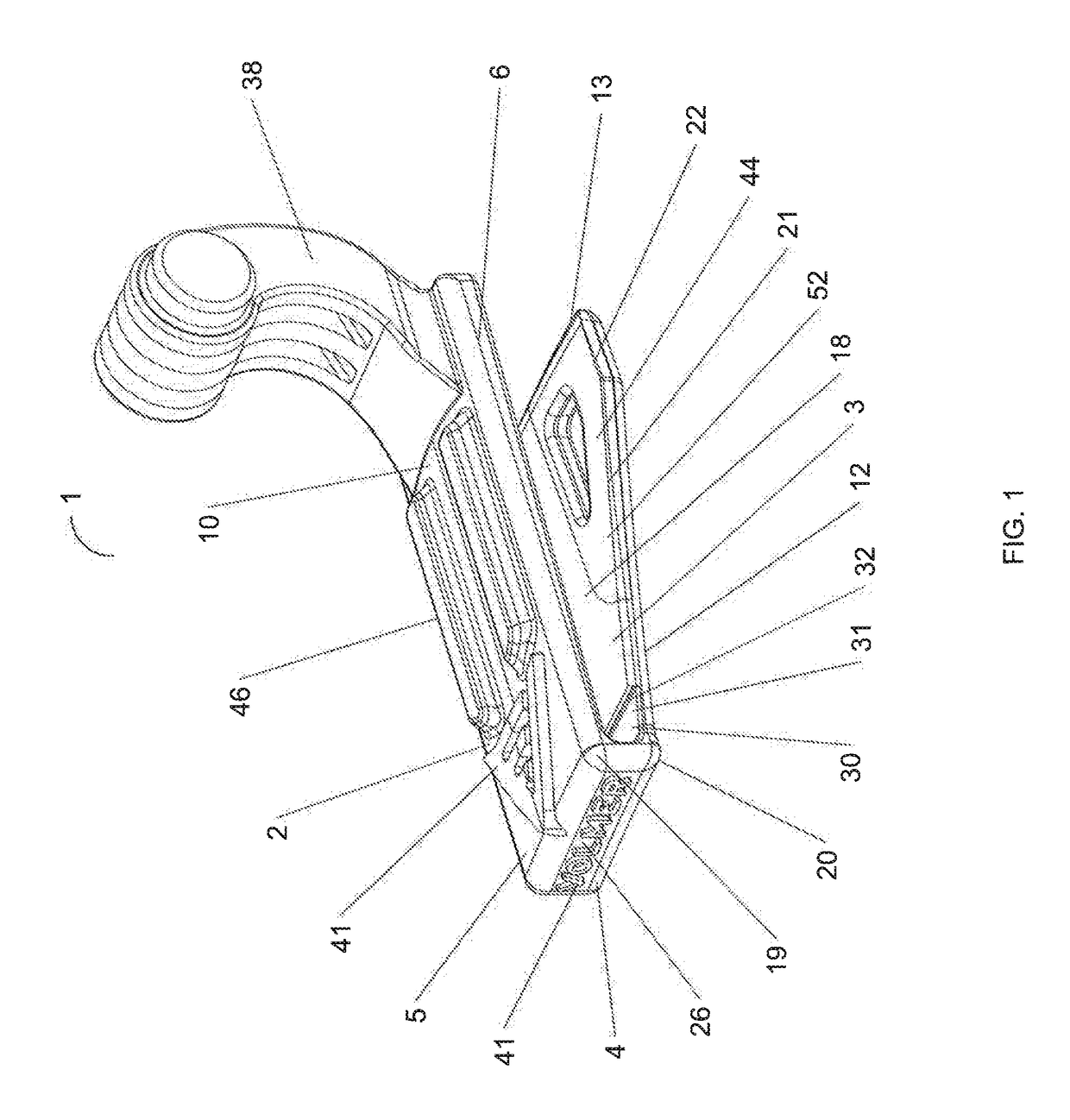
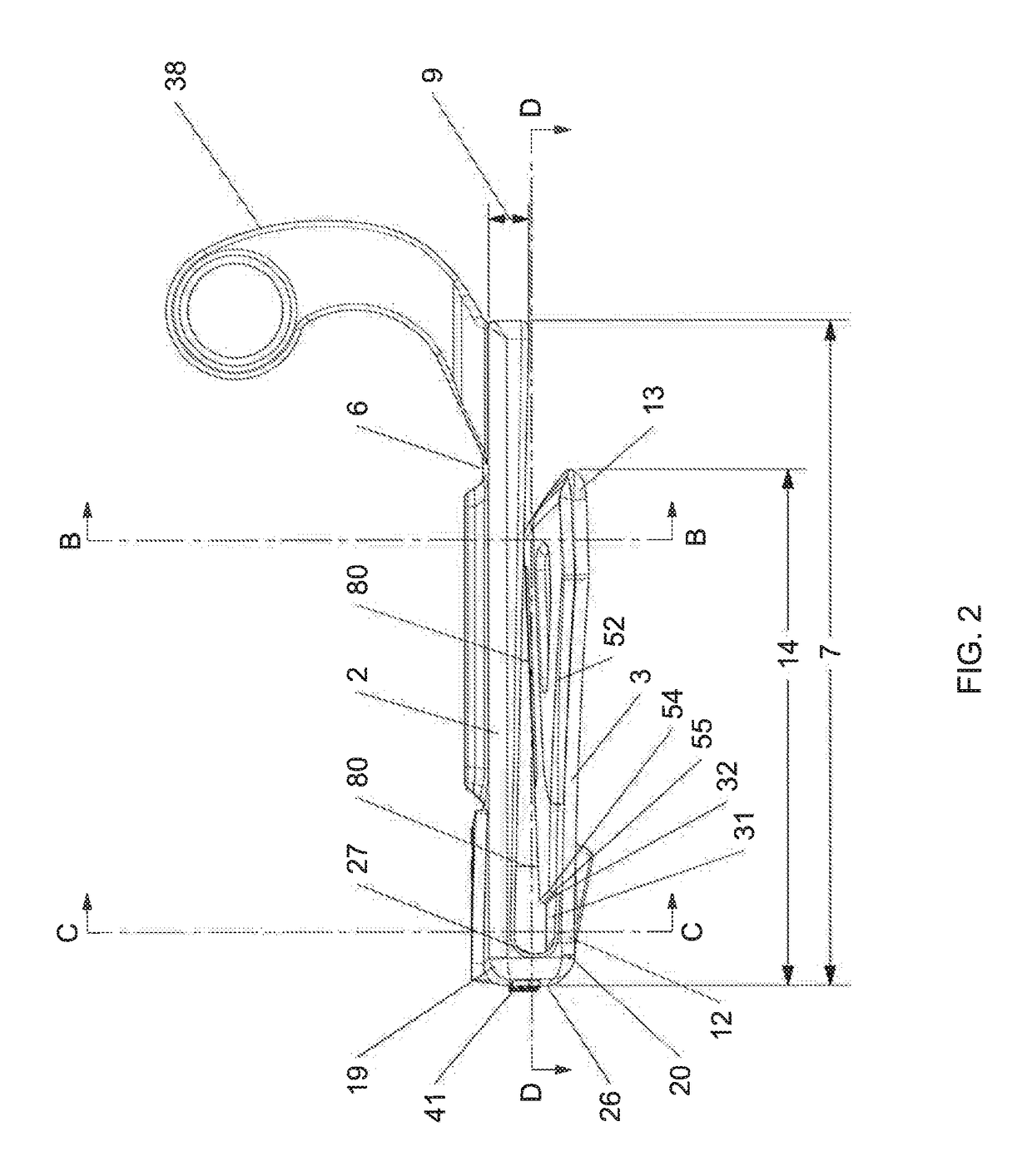
[0050]A preferred embodiment of the present invention accessory mounting clip 1 and its preferred constituent features are shown in FIGS. 1-10, FIGS. 13A-13D and FIGS. 14-17. For reference purposes the term “distal end” is used to refer to that portion of the clip or its components that are furthest away from a user's head when the clip is deployed on the brim of a hat. The term “proximal end” is used to refer to that portion of the clip or its components that are nearest the user's head when the clip is deployed on the brim of a hat. The preferred embodiment clip works particularly well when used to mount accessories on the brim (a / k / a bill) 71 of a baseball cap 70 such as is shown in FIGS. 12A and 12B. As shown in FIGS. 12A and 12B, brim 71 typically has a front edge 72 that has a front to back curvature of certain radius. Brim 71 also has a thickness 74. Brim 71 also has a transverse curvature or bend of a certain radius that is best discerned when looking at the cap head on.

[005...


PUM


Abstract

A clip for mounting devices on a hat brim includes a first and second panel. The panels are each resiliently connected to a nose portion and separated by a spacing that tapers to a contact point from the distal portions of the panels to their proximal portions. The second panel has a wedge-shaped portion in which the width of the panel increases from its distal end to its proximal end. The bottom surface of the first panel is concave. The top surface of the second panel is convex. The clip can include connecting structure at its proximal end to allow for the interchangeable attachment of mounting structure for a variety of accessory devices. The clip can also include a mount for holding a microphone or microphone jack to allow the clip to hold a microphone in electrical communication with a camera mounted to the clip.

Description

[0001]This application is a continuation in part of U.S. patent application Ser. No. 14 / 921,719 filed on Oct. 23, 2015, now U.S. Pat. No. 9,596,926, the entire contents of which application are incorporated herein by reference. This application also claims the benefit and fully incorporates by reference the disclosure and contents of U.S. Provisional Patent Application No. 62 / 323,882.STATEMENT REGARDING FEDERALLY SPONSORED RESEARCH OR DEVELOPMENT[0002]Not applicable.SEQUENCE LISTING, TABLE OR COMPUTER PROGRAM ON COMPACT DISC[0003]Not applicable.FIELD OF INVENTION[0004]This invention relates generally to accessory mounts and more specifically to those mounts intended for attachment to headwear.BACKGROUND OF THE INVENTION[0005]The deployment of a headlamp positioned in the vicinity of a user's forehead is a long-known technique to provide hands free lighting when needed. One technique for deploying such hands-free lighting is to attach a headlamp to elastic bands that can circumscribe...

Claims


Application Information

Patent Timeline
Patent Type & Authority Patents(United States)
IPC IPC(8): A42B1/24F16B2/00A45F5/02F16B2/22H04R1/08
CPCA42B1/24A45F5/02F16B2/005F16B2/22H04R1/08Y10T24/1394A45F2005/027A45F2005/028A45F2200/0516A45F2200/0533A45F2005/025
Inventor VOLMER, JASON R.
Owner VOLMER ENTERPRISES INC
Why Eureka
Try Eureka