Keyboard

a technology of keyboards and metal bottom plates, applied in the field of keys, can solve the problems of affecting the operation of the keyboard, the configuration of the conventional guiding connection structure with a metal bottom plate may not meet the demand, and the keyboard to shake and tilt.

Active Publication Date: 2021-11-23
CHICONY ELECTRONICS
View PDF4 Cites 1 Cited by
  • Summary
  • Abstract
  • Description
  • Claims
  • Application Information

AI Technical Summary

Benefits of technology

[0007]An aspect of the disclosure is to provide a keyboard which can effectively solve the aforementioned problems.
[0023]Accordingly, in the keyboard of the present disclosure, the guiding connection structure is connected to the plastic engaging member disposed on the base plate, instead of being connected to the hooks on the metal bottom plate as used in the conventional keyboard. The plastic engaging member disposed on the base plate of the present disclosure can increase the structural strength of the base plate, so as to effectively avoid the problem of deformation of the base plate caused by pressing when assembling the guiding connection structure or pressing the keycap, thereby allowing the base plate to be further thinned to achieve the purpose of being light and thin. Moreover, the assembly tolerance between the plastic engaging member and the guiding connection structure can be controlled simply by the manufacturing precision of the plastic engaging member itself, and does not be deeply affected by the processing precision of bending the hooks as the conventional keyboard does, so the assembly precision of the keyboard of the present disclosure is improved.

Problems solved by technology

Therefore, the machining precision of bending the hooks will have a great impact on the assembly tolerance between the guiding connection structure and the hooks, which will often cause the keyswitch to shake and tilt.
Moreover, the aforementioned bottom plate and guiding connection structure are generally made of metal material, so when the keyboard is used, noises of knocking metal are often generated.
In addition, under the current development trend of the keyboard towards light weight and thinning, the configuration of the conventional guiding connection structure with a metal bottom plate may not meet the demand.
For example, if the thickness of the metal bottom plate is reduced in the foregoing configuration to meet the weight reduction requirement, the strength of the metal bottom plate is also reduced, which may result in failure to perform processing such as stamping and bending on the metal bottom plate.

Method used


Image

  • Keyboard
  • Keyboard
  • Keyboard

Examples


Embodiment Construction

[0039]Reference will now be made in detail to the present embodiments of the disclosure, examples of which are illustrated in the accompanying drawings. Wherever possible, the same reference numbers are used in the drawings and the description to refer to the same or like parts. However, specific structural and functional details disclosed herein are merely representative for purposes of describing exemplary embodiments, and thus may be embodied in many alternate forms and should not be construed as limited to only exemplary embodiments set forth herein. Therefore, it should be understood that there is no intent to limit exemplary embodiments to the particular forms disclosed, but on the contrary, exemplary embodiments are to cover all modifications, equivalents, and alternatives falling within the scope of the disclosure.

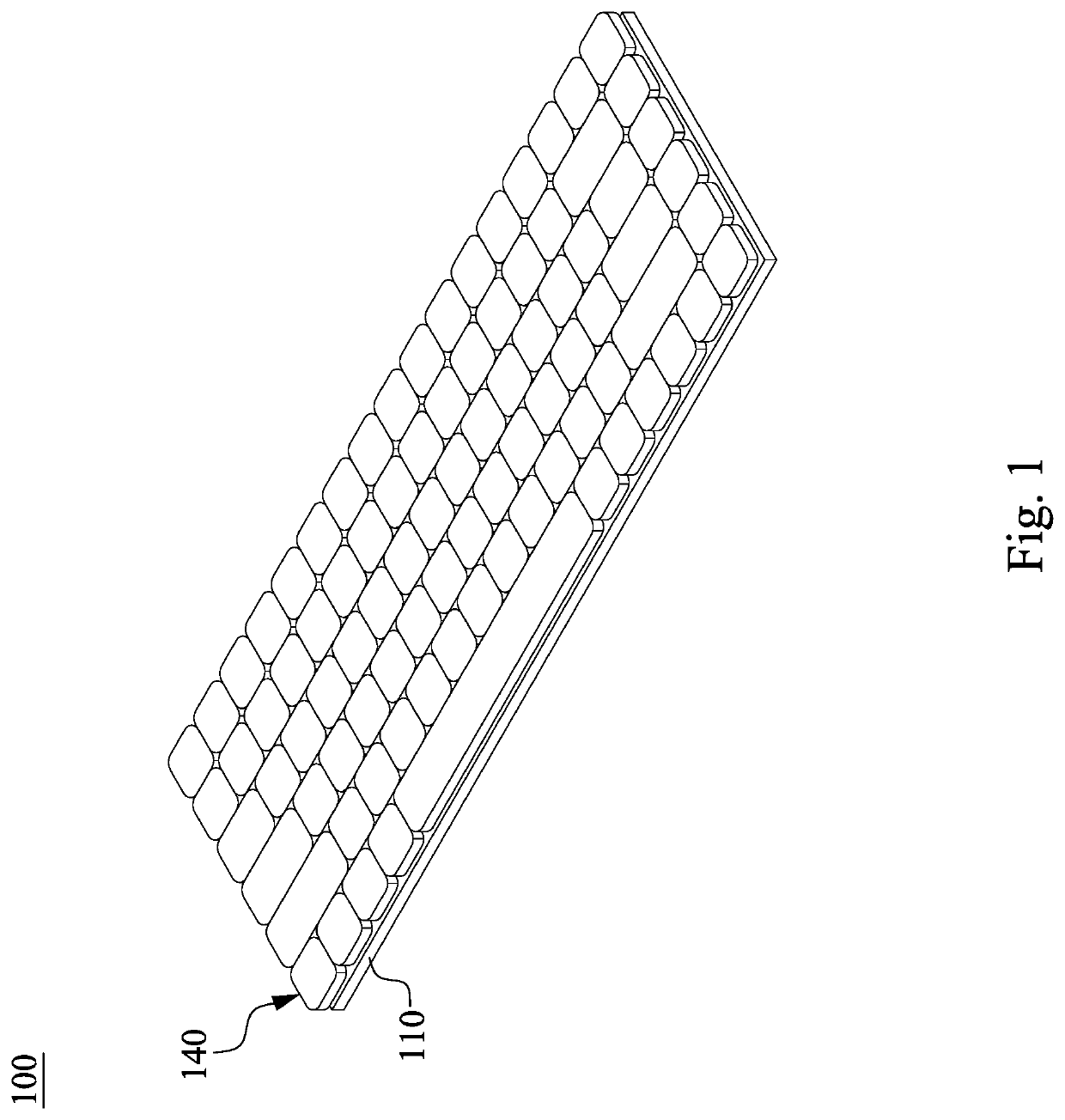
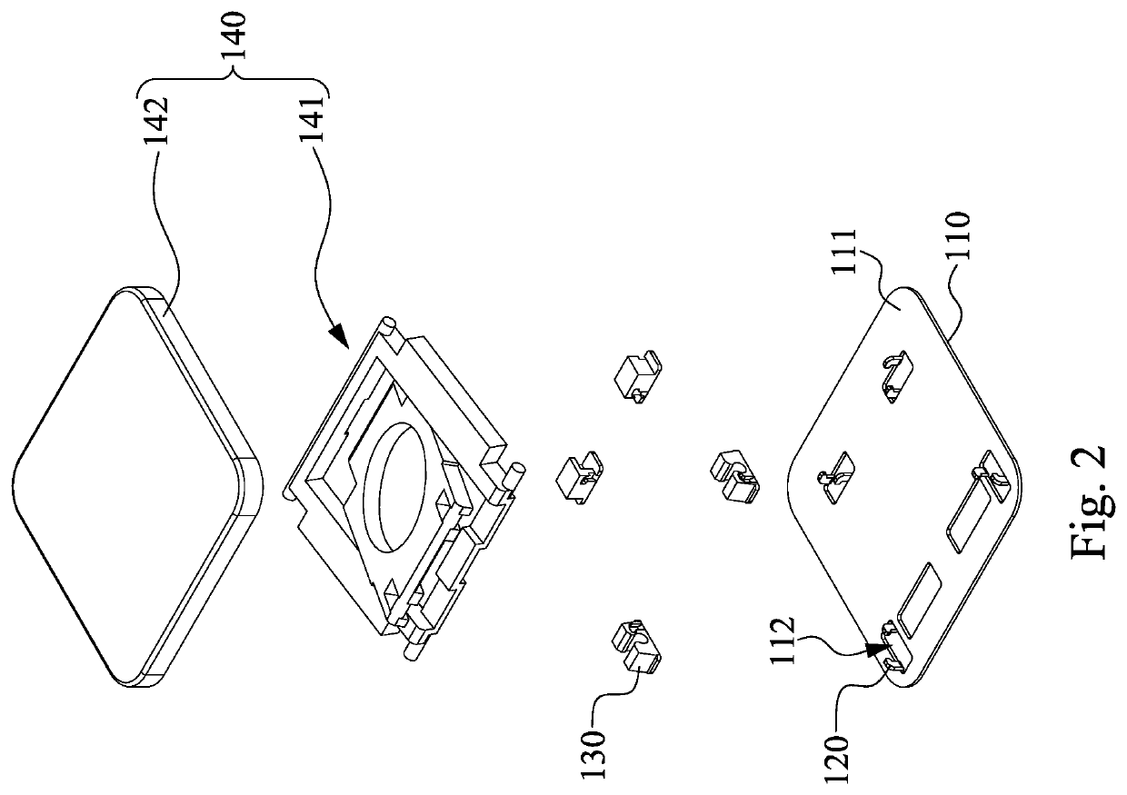
[0040]Reference is made to FIGS. 1 and 2. FIG. 1 is a perspective view of a keyboard 100 according to an embodiment of the disclosure. FIG. 2 is a partial exploded...


PUM


Abstract

A keyboard includes a base plate, a hook structure, and a plastic engaging member. The base plate has a top surface. The hook structure is connected to the base plate and raised relative to the top surface. The plastic engaging member is located on the top surface and fixed to at least a part of the hook structure.

Description

CROSS-REFERENCE TO RELATED APPLICATION[0001]This application claims priority to Taiwan Application Serial Number 108121354, filed Jun. 19, 2019, which is herein incorporated by reference.BACKGROUNDTechnical Field[0002]The present disclosure relates to a keyboard.Description of Related Art[0003]For a keyswitch on a keyboard, in order to balance the force applied onto the keyswitch by a user, a kind of guiding connection structure is usually disposed under the keycap of the keyswitch, so as to guide the keycap to vertically move. As such, no matter being applied at an edge or a corner of the keycap, the force can be spread evenly across the entire surface of the keycap, which makes it easy to press the entire keyswitch and makes it easier for the user to operate the keyswitch.[0004]In general, the foregoing guiding connection structure is often fixed in the keyboard by engaging with hooks formed on a bottom plate. A conventional method of manufacturing the bottom plate having the hook...

Claims


Application Information

Patent Timeline
Patent Type & Authority Patents(United States)
IPC IPC(8): H01H3/12H01H13/705H01H13/14
CPCH01H13/705H01H13/14H01H3/125H01H2221/062H01H2229/048H01H2229/064
Inventor HSIEH, CHAO-CHINCHAN, CHUN-CHIEH
Owner CHICONY ELECTRONICS
Why Eureka
Try Eureka