Beam deflection device

a beam deflection device and beam deflection technology, applied in the field of adjustable beam deflection devices, can solve the problems of large frictional losses in the ball bearings, large loss of excitation light or detected light, and one of the mirrors can be positioned at the location of the pupil image, so as to achieve fast, efficient control of light beams, and largely maintenance-free and wear-free

Inactive Publication Date: 2005-02-17
LEICA MICROSYSTEMS CMS GMBH
View PDF8 Cites 0 Cited by
  • Summary
  • Abstract
  • Description
  • Claims
  • Application Information

AI Technical Summary

Benefits of technology

[0011] It is an object of the present invention to provide a beam deflection device that permits fast, efficient control of a light beam and is largely maintenance-free and wear-free.

Problems solved by technology

Among the disadvantages of beam deflection devices based on galvanometer mirrors are the large frictional losses in the ball bearings.
Neutral beam splitters have the disadvantage that depending on the splitting ratio, a great deal of excitation light or detected light is lost.
Beam deflection devices based on two mirrors arranged one after another have the disadvantage that only one of the mirrors can be positioned at the location of the pupil image.
This necessarily results in an aberration.

Method used


Image

  • Beam deflection device
  • Beam deflection device
  • Beam deflection device

Examples


Embodiment Construction

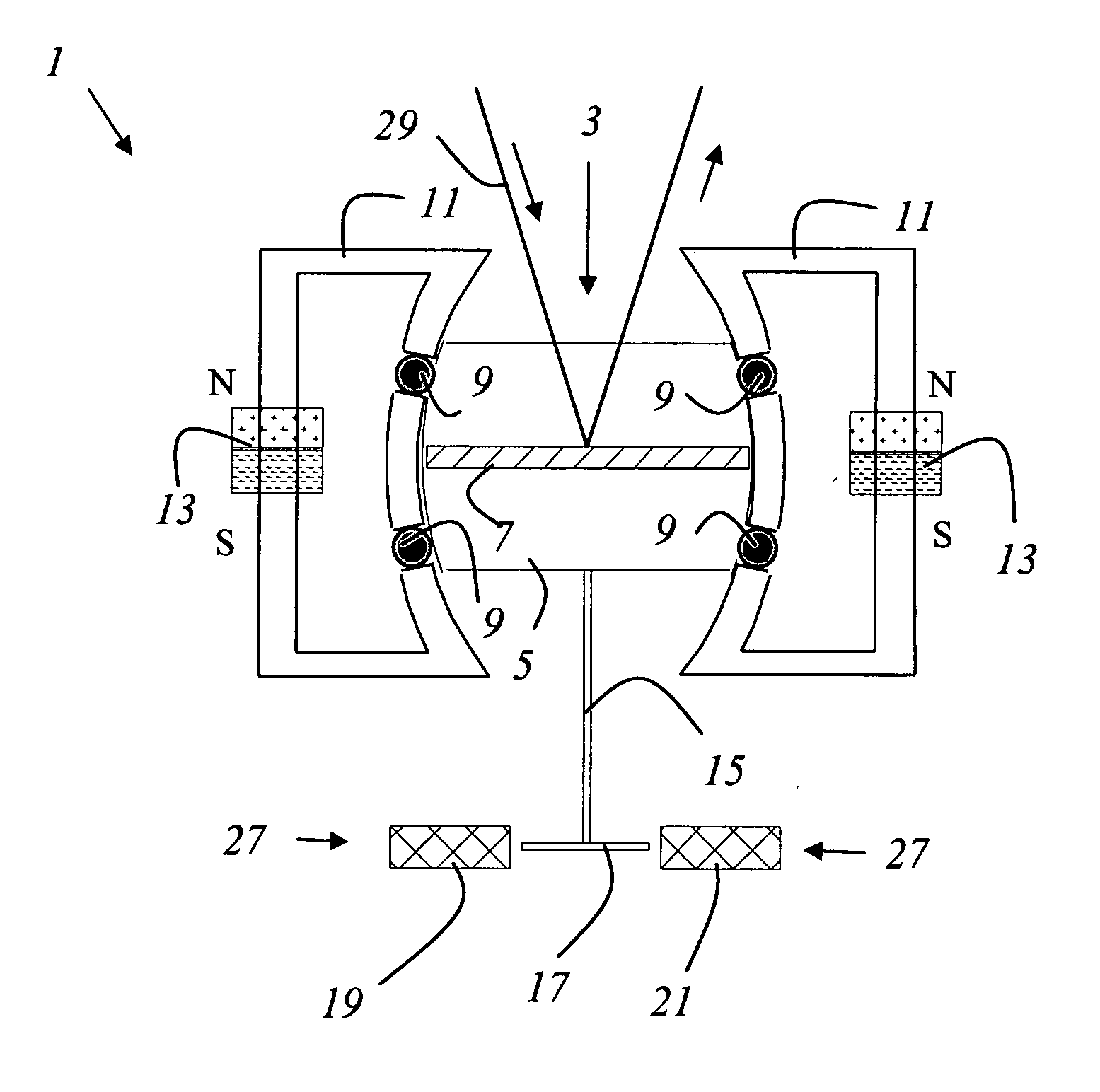
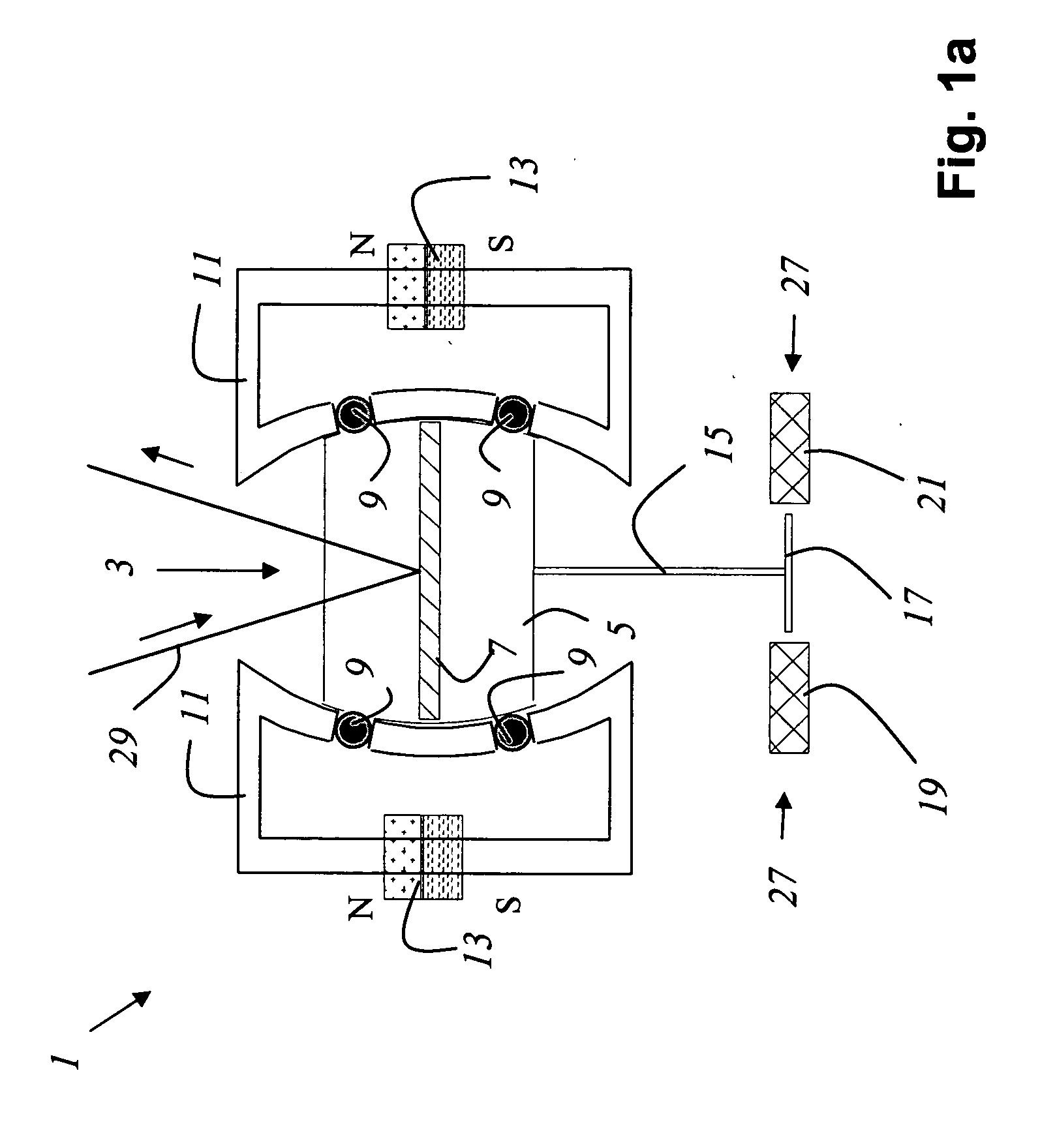
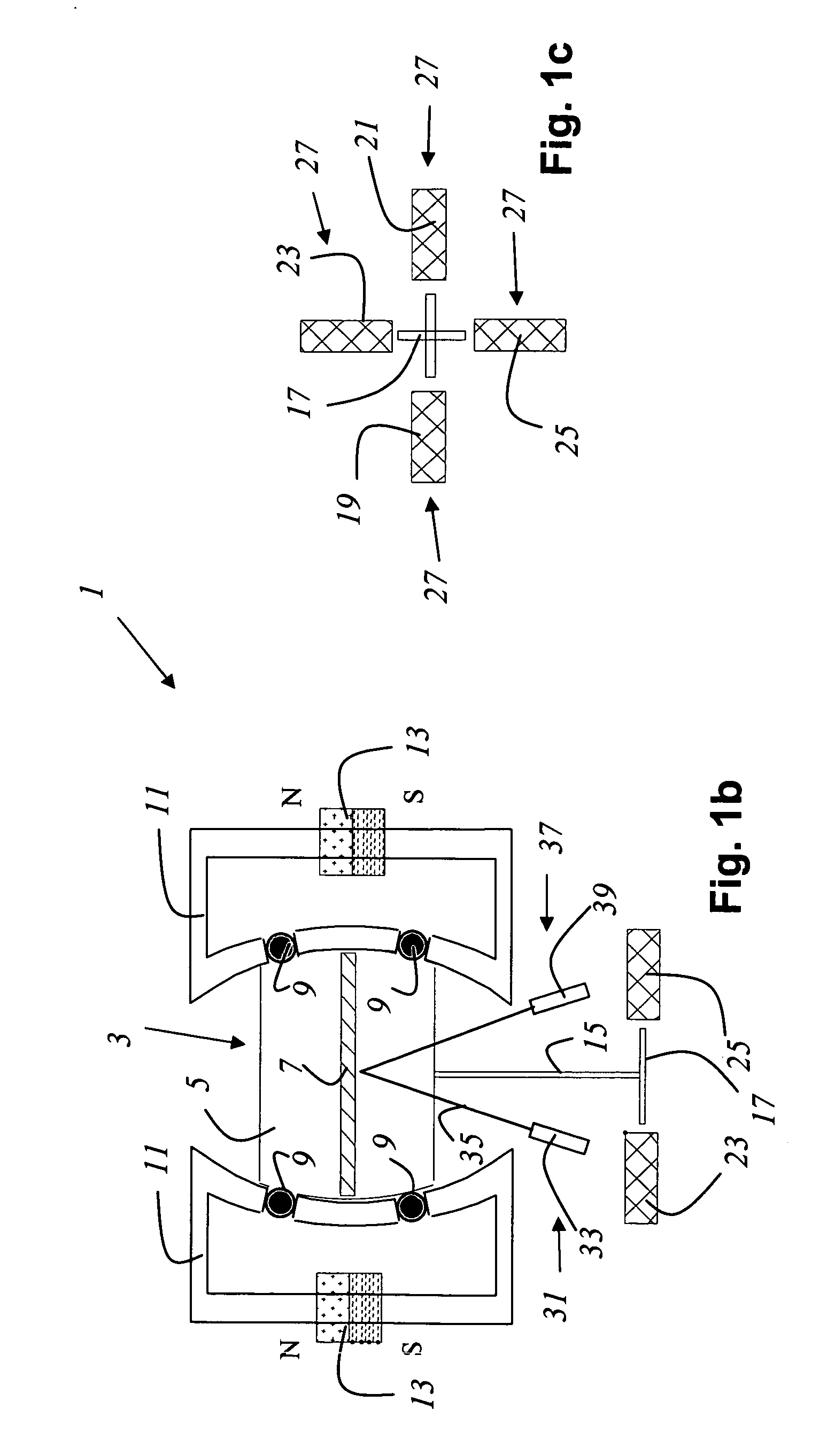
[0032]FIG. 1a shows a beam deflection device 1 according to the present invention in an X-Z section. Beam deflection device 1 comprises a deflection means 3 that is made up of a nonmagnetic mirror support 5 and a mirror 7 mounted thereon. Nonmagnetic mirror support 5 floats in a ferrofluid 9 and is located inside a yoke 11 of an annular magnet 13; as a result of the magnetic field, the ferrofluid collects in the gap between deflection means 3 and yoke 11. The magnetic field of annular magnet 13 exerts a force on the ferrofluid with magnetic flux B, so that the density of the magnetic field lines likewise imposes a dense change on the ferrofluid and thus a pressure on mirror support 5, so that mirror 5 centers itself in the middle.

[0033] Deflection means 3 comprises a control lever 15 at whose end is mounted a magnetic component 17 that is cross-shaped. The beam deflection device comprises four coils 19, 21, 23, 25 as drive means 27. With coils 19-25, a force can be exerted on magne...


PUM


Abstract

A deflection means which is rotatably and/or pivotably mounted in a bearing which comprises a Ferrofluid. The deflection means is part of an adjustable beam deflection device for deflecting a light beam. The deflection means is rotatable and/or pivotable about several axes.

Description

CROSS REFERENCE TO RELATED APPLICATIONS [0001] This application claims priority to German patent application 103 37 297.0, the entire disclosure of which is hereby incorporated by reference herein. FIELD OF THE INVENTION [0002] The invention concerns an adjustable beam deflection device for deflecting a light beam and a scanning microscope. BACKGROUND OF THE INVENTION [0003] Beam deflection devices are known in optics in a great variety of embodiments. Many beam deflection devices, in particular those in which rapid deflection of light beams is important, contain galvanometer mirrors. Among the disadvantages of beam deflection devices based on galvanometer mirrors are the large frictional losses in the ball bearings. As a consequence of its design, the return spring in the galvanometer positioning elements is not arranged symmetrically; with rapid oscillations in particular, this becomes perceptible as a difference in motion between the forward and return strokes of the galvanometer...

Claims


Application Information

Patent Timeline
Patent Type & Authority Applications(United States)
IPC IPC(8): G02B21/06G02B26/08G02B26/10
CPCG02B26/0816
Inventor RYGIEL, REINER
Owner LEICA MICROSYSTEMS CMS GMBH
Why Eureka
Try Eureka