Lift drive device

a technology of lifting drive and gearbox, which is applied in the direction of friction gearing, toothed gearing, gearing, etc., can solve the problems of heavy metal components, awkward installation, and heavy weight of metal components, and achieves simple and inexpensive manufacturing, improved drive, and strong and reliable

Active Publication Date: 2005-03-17
HARMAR MOBILITY
View PDF12 Cites 15 Cited by
  • Summary
  • Abstract
  • Description
  • Claims
  • Application Information

AI Technical Summary

Benefits of technology

What is desired is an improved drive for use in lift and lower devices, whether seat bearing, platform bearing or even elevator style lifts. Such a drive will be simple and inexpensive to make while at the same time being strong and reliable. Most preferably such a drive will be more efficient than the conventional prior art gear and tra

Problems solved by technology

These type of devices have met with significant success, but suffer from a number of drawbacks.
As can be appreciated, these devices, among other things tend to permit a mobility challenged person to remain in their own home, even though they may no longer be able to climb the stairs between the upstairs and the downstairs.
Such metal components are heavy and somewhat expensive.
Thus, it can be both costly and awkward to ship the material to where it is needed.
Its weight also makes it awkward and difficult to install.
Further, the

Method used


Image

  • Lift drive device
  • Lift drive device
  • Lift drive device

Examples


Embodiment Construction

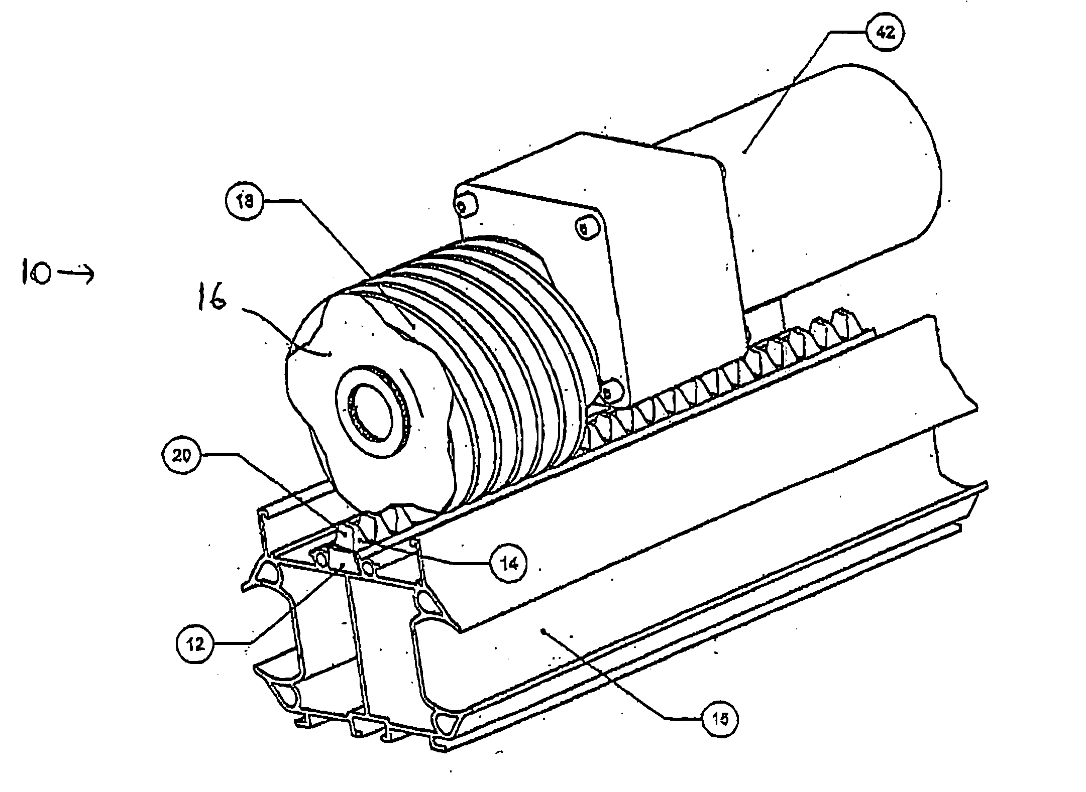
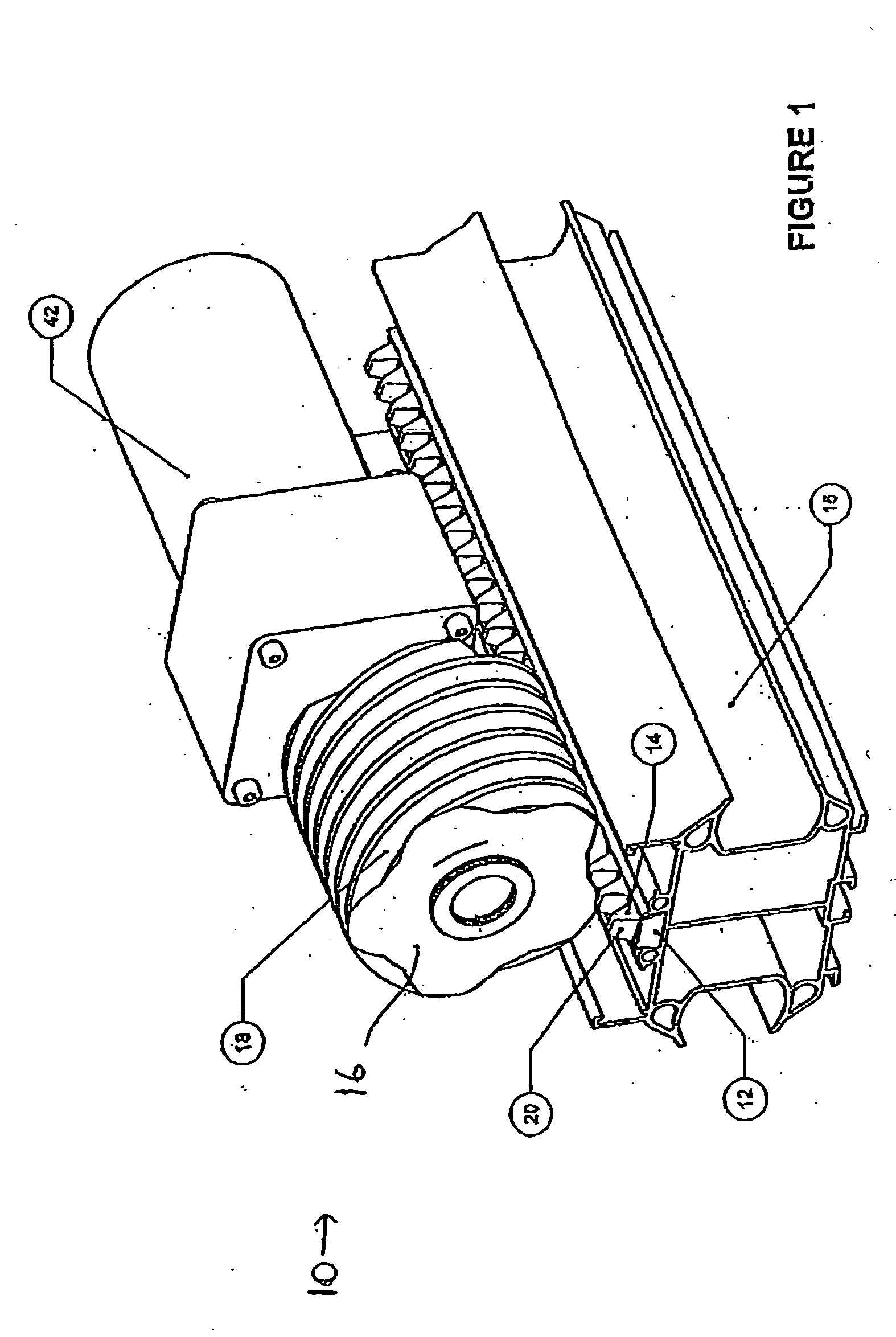
FIG. 1 shows a lift drive device 10 according to the present invention. The lift drive device 10 includes three main elements, namely a track 12 having teeth 14, incorporated into a rail 15, a drive element 16 having spiral drive threads 18 and a motor 42. In this sense the row of teeth form a track, and the track of teeth form part of the rail and are integrated therewith. In the present specification the term lift drive is used, although the drive of the present invention can both lift and lower. The drive of the present invention is most suitable for lifting along an inclined plane, although vertical lifts are also comprehended. As explained in more detail below, by reversing the direction of rotation of the drive element, the present invention can be used to move in both directions along a rail 15 having a track 12.

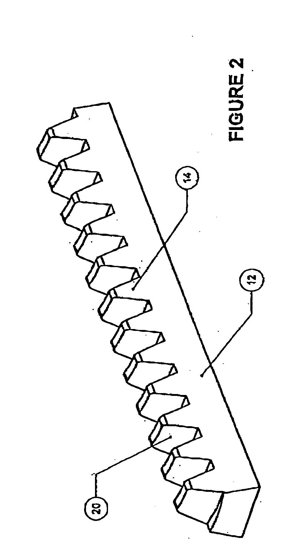
FIG. 2 shows the teeth 14 of the track 12 in greater detail. Most preferably the teeth are integrally formed with the track and are made from a moulded plastic. Many ...


PUM


Abstract

A lift drive comprising: a spiral drive element having an axis of rotation, a rack having teeth sized and shaped to be engaged by the spiral drive element, the rack having a longitudinal axis parallel to the axis of rotation, and a motor to rotate the spiral drive element, wherein upon the spiral drive element-rotating, one of the spiral drive element and the rack moves relative to the other along the longitudinal axis.

Description

FIELD OF THE INVENTION This invention relates generally to the field of drive devices of the sort that are used to move goods or people short distances from one place to another. Most particularly this invention relates to drive devices of the sort that may be used in stair lifts or elevators for use by mobility challenged people. BACKGROUND OF THE INVENTION Currently many developed western economies have aging populations. Improved health care and advanced medical technologies are contributing to longer lives on average. As time passes, more and more people reach an advanced age. With advanced age comes reduced mobility, for example, less ability to get up and down stairs in a family home. A modern trend in managed health care is home care, in which individuals are encouraged to live at home rather than in an institution. Home care generally includes a higher quality of life and can be less expensive. Therefore, there is a growing need for devices to enhance the mobility of senio...

Claims


Application Information

Patent Timeline
IPC IPC(8): B66B9/02F16H19/00F16H19/04F16H25/24
CPCB66B9/025Y10T74/19828F16H25/2409F16H19/04
Inventor MOLNAR, GORDONSHAW, PETER
Owner HARMAR MOBILITY
Why Eureka
Try Eureka