Polarization scrambler unit and multi-repeater transmission system incorporating the same

a transmission system and scrambler technology, applied in electromagnetic repeaters, instruments, optical elements, etc., can solve the problems of multi-repeater transmission systems unavailable, gain polarized-light dependency per optical amplification repeater has reached the limit, and the trouble and loss caused by failure of polarization scrambler can be minimized, and the gain polarized-light dependency of the whole multi-repeater transmission system can be enhanced.

Inactive Publication Date: 2005-04-28
NEC CORP
View PDF5 Cites 4 Cited by
  • Summary
  • Abstract
  • Description
  • Claims
  • Application Information

AI Technical Summary

Benefits of technology

[0010] A first objective of the present invention is to provide a technique by which trouble and loss caused by failure of a polarization scrambler can be minimized. A second objective of the present invention is to provide a technique by which gain polarized-light dependency of the whole multi-repeater transmission system can be enhanced regardless of gain polarized-light dependency per optical amplification repeater.

Problems solved by technology

However, conventional technique has the following problems.
According to the conventional technique, a failure polarization scrambler has to be exchanged for a new one, which is troublesome and renders the multi-repeater transmission system unavailable until the exchange is completed.
As a result, the gain polarized-light dependency per optical amplification repeater has reached the limit.

Method used


Image

  • Polarization scrambler unit and multi-repeater transmission system incorporating the same
  • Polarization scrambler unit and multi-repeater transmission system incorporating the same
  • Polarization scrambler unit and multi-repeater transmission system incorporating the same

Examples


first embodiment

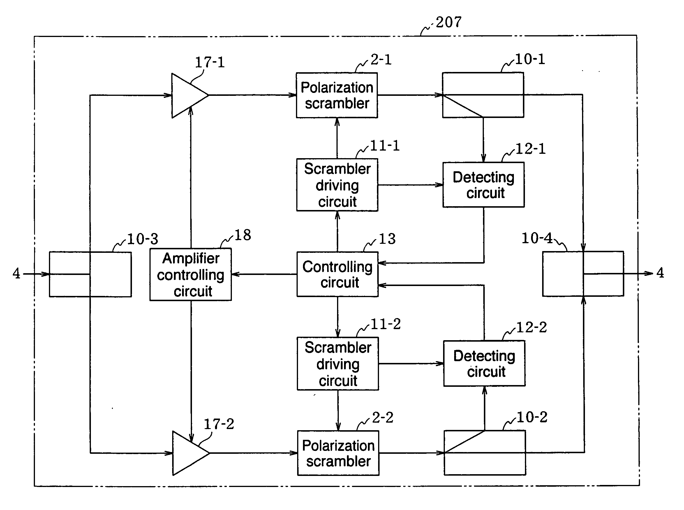
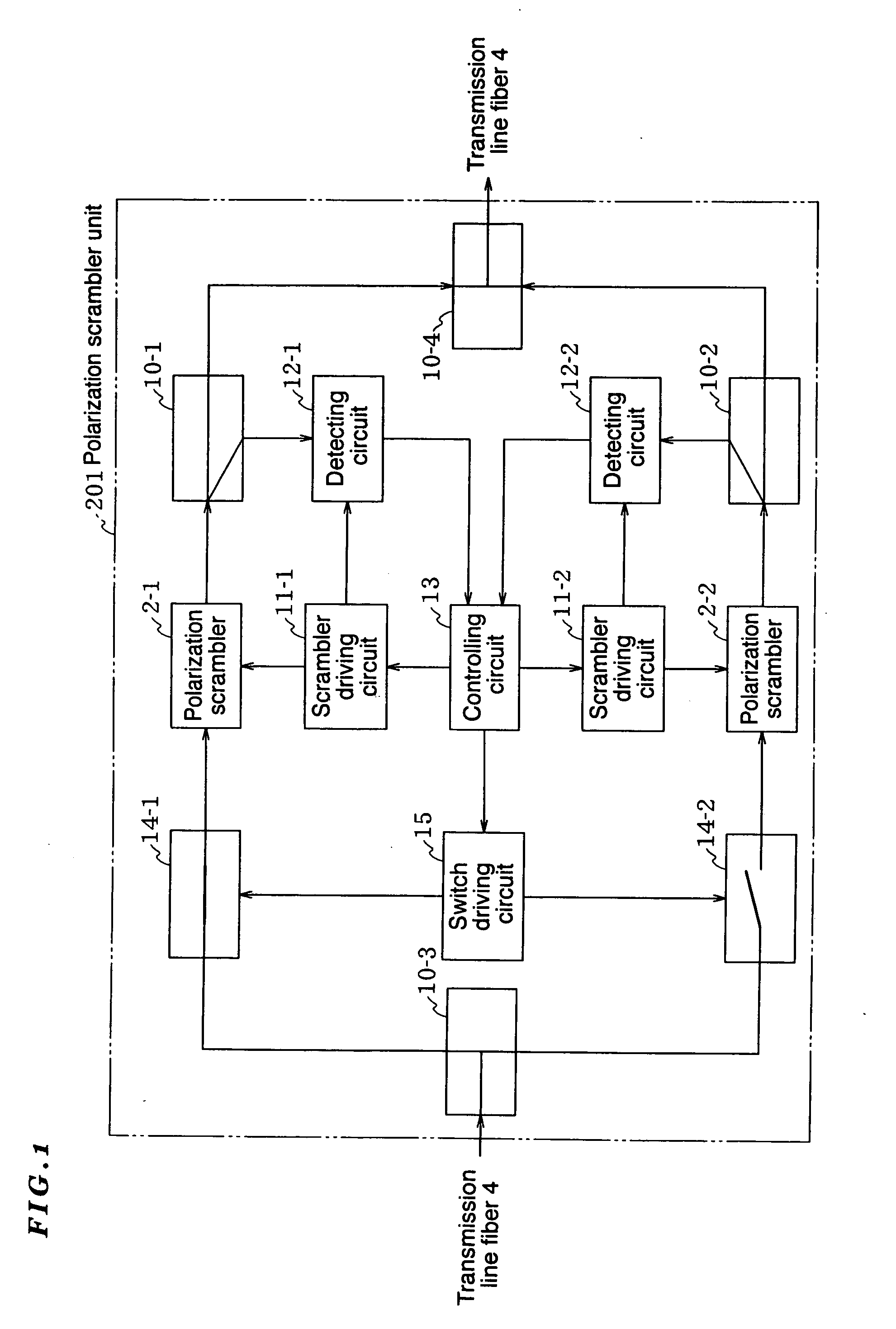
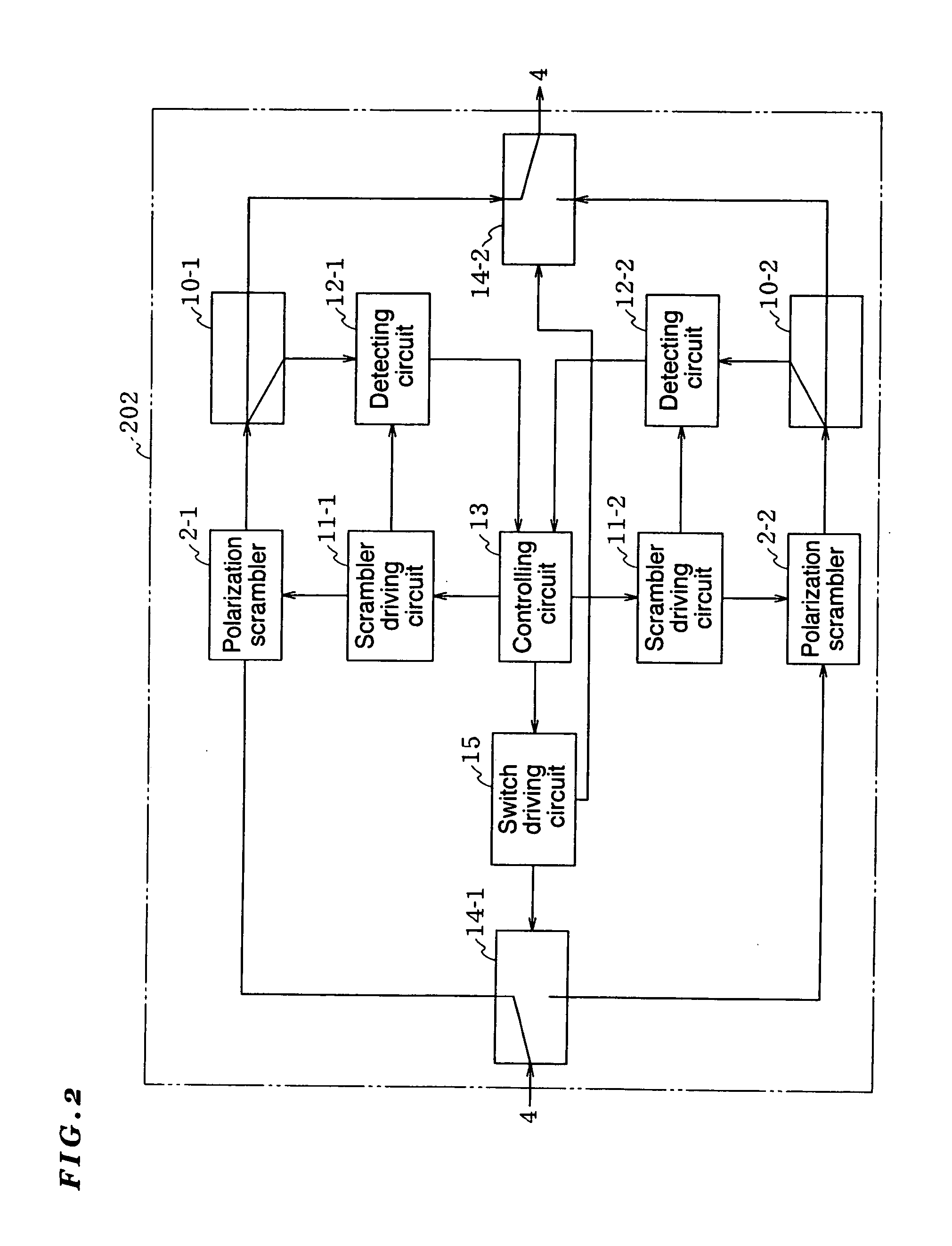
[0032] A polarization scrambler unit 201 of the first embodiment is provided with: two polarization scramblers 2-1 and 2-1; a switching unit (described later) for coupling either one of the polarization scramblers 2-1 and 2-1 to a transmission line fiber 4; a detection unit (described later) for detecting an output signal from the polarization scrambler 2-1 (or the polarization scrambler 2-2) coupled to the transmission line fiber 4; and a controlling unit (described later) for switching, by the switching unit, between the polarization scrambler 2-1 and the polarization scrambler 2-2 when a false output signal is detected by the detection unit.

[0033] The switching unit is provided with optical switches 14-1 and 14-2 which are inserted between the transmission line fiber 4 and the polarization scramblers 2-1 and 2-2, respectively; a switch driving circuit 15 for opening or closing the optical switches 14-1 and 14-2; an optical coupler 10-3 for branching light from the transmission li...

second embodiment

[0051] A polarization scrambler unit 204 differs from that of the second embodiment in that an optical coupler 10-5 is inserted between an optical switch 14-1 and a polarization scrambler 2-1, and a clock detecting circuit 16-1 is inserted between a branched output terminal of the optical coupler 10-5 and an input terminal of a scrambler driving circuit 11-1 (an auxiliary system is also configured in the same manner).

[0052] The clock detecting circuit 16-1 detects a clock component that is synchronous with the main signal from the signal branched from the optical coupler 10-5, and controls the scrambler driving circuit 11-1 in synchronous with this component (the auxiliary system also works in the same manner). Since the clock component synchronous with the main signal is used, polarization scramble can be performed at high speed.

[0053]FIG. 5 is a block diagram showing a fifth embodiment of a polarization scrambler unit according to the present invention. Hereinafter, the fifth emb...

third embodiment

[0054] A polarization scrambler unit 205 differs from that of the third embodiment in that a polarization scrambler 2-3 is inserted between an optical coupler 10-5 and a polarization scrambler 2-1 and connected to a scrambler driving circuit 11-3, which in turn is connected to a clock detecting circuit 16-1 (an auxiliary system is also configured in the same manner). The polarization scrambler unit 205 allows both high-speed polarization scramble by the polarization scrambler 2-3 and low-speed polarization scramble by the polarization scrambler 2-1 at the same time (the auxiliary system also works in the same manner).

[0055]FIG. 6 is a block diagram showing a sixth embodiment of a polarization scrambler unit according to the present invention. Hereinafter, the sixth embodiment will be described with reference to this drawing. The same or similar components as those shown in FIG. 4 will be denoted by the same reference numerals and thus the descriptions thereof are omitted.


PUM

PropertyMeasurementUnit
optical lossaaaaaaaaaa
transmission lossaaaaaaaaaa
temperatureaaaaaaaaaa

Abstract

The present invention minimizes trouble and loss caused by a failure polarization scrambler. A polarization scrambler unit 201 of the invention is provided with: two polarization scramblers 2-1 and 2-1; a switching unit for coupling either one of the polarization scramblers 2-1 and 2-1 to a transmission line fiber 4; a detection unit for detecting an output signal from the polarization scrambler 2-1 (or the polarization scrambler 2-2) coupled to the transmission line fiber 4; and a controlling unit for switching, via the switching unit, between the polarization scramblers 2-1 and 2-2 whenever a false output signal is detected by the detection unit. Thus, the polarization scrambler unit 201 has a redundant structure.

Description

FIELD OF THE INVENTION [0001] The present invention relates to a polarization scrambler unit for correcting gain polarized-light dependency of an optical amplification repeater, and to a multi-repeater transmission system incorporating the same. BACKGROUND OF THE INVENTION [0002] In general, a polarization state of an optical signal propagating through a multi-repeater transmission system is an elliptically polarized wave which has a major axis and a minor axis perpendicular to the major axis. When an optical amplification repeater is operated under a gain saturation state, and the powers differ between directions along the major and minor axes of the polarized-light of signal, the gain saturation state varies in the direction of polarization of light due to the power difference. As a result, the gain becomes unequal, and thus the amplification signal power and noise power vary according to the polarization state of the optical signal input into the optical amplification repeater. [...

Claims


Application Information

Patent Timeline
Patent Type & Authority Applications(United States)
IPC IPC(8): G02F1/01G02B6/34H04B10/032H04B10/07H04B10/25H04B10/2507H04B10/29
CPCH04B10/2572G02B6/2786
Inventor YAMAGUCHI, SHOHEI
Owner NEC CORP
Why Eureka
Try Eureka