Polarization scrambler unit and multi-repeater transmission system incorporating the same
a transmission system and scrambler technology, applied in multiplex communication, electromagnetic repeaters, instruments, etc., can solve the problems of multi-repeater transmission system unavailable, gain polarized-light dependency per optical amplification repeater has reached the limit, and the trouble and loss caused by failure of polarization scrambler can be minimized, and the gain polarized-light dependency of the whole multi-repeater transmission system can be enhanced.
- Summary
- Abstract
- Description
- Claims
- Application Information
AI Technical Summary
Benefits of technology
Problems solved by technology
Method used
Image
Examples
first embodiment
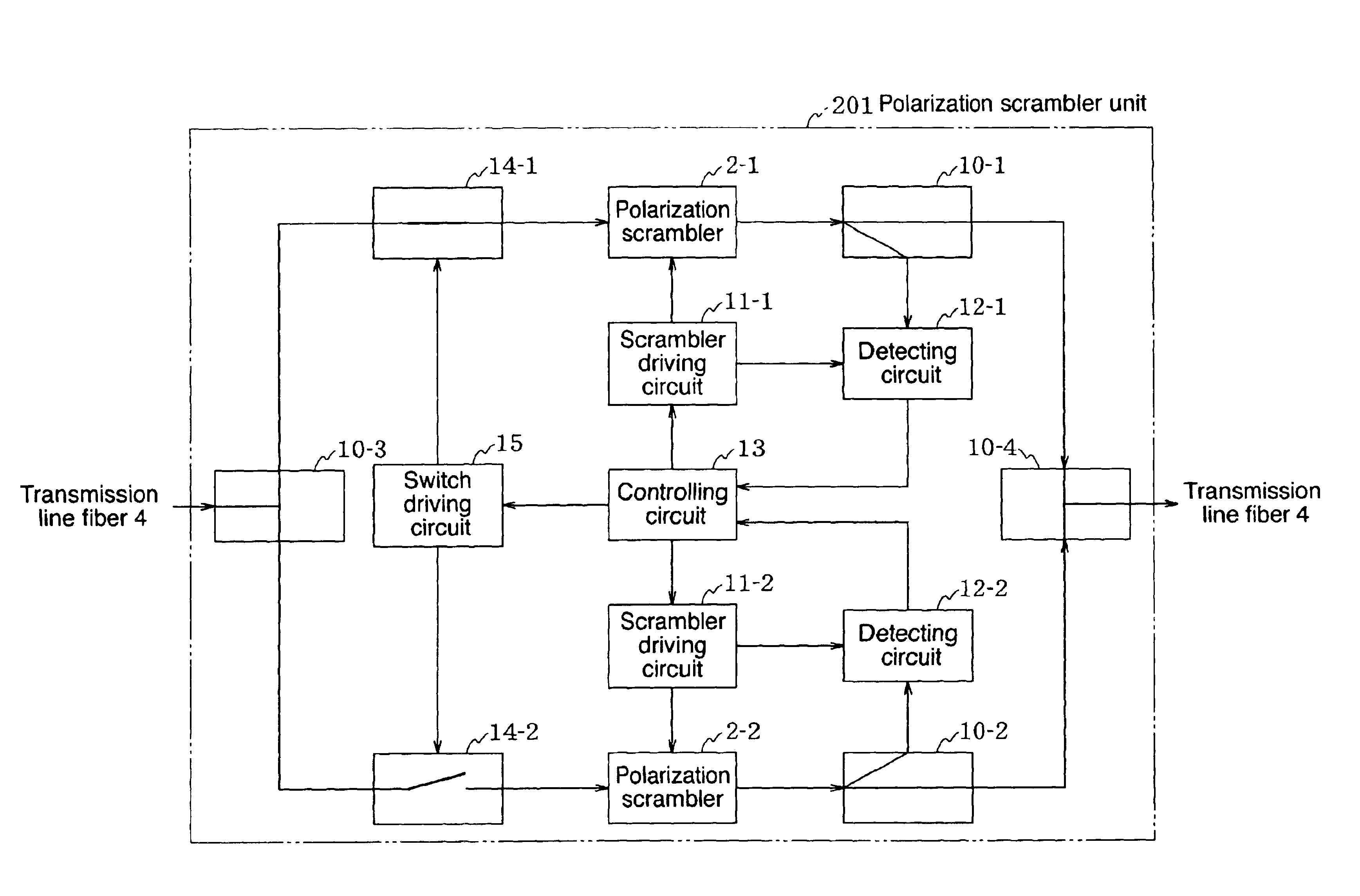
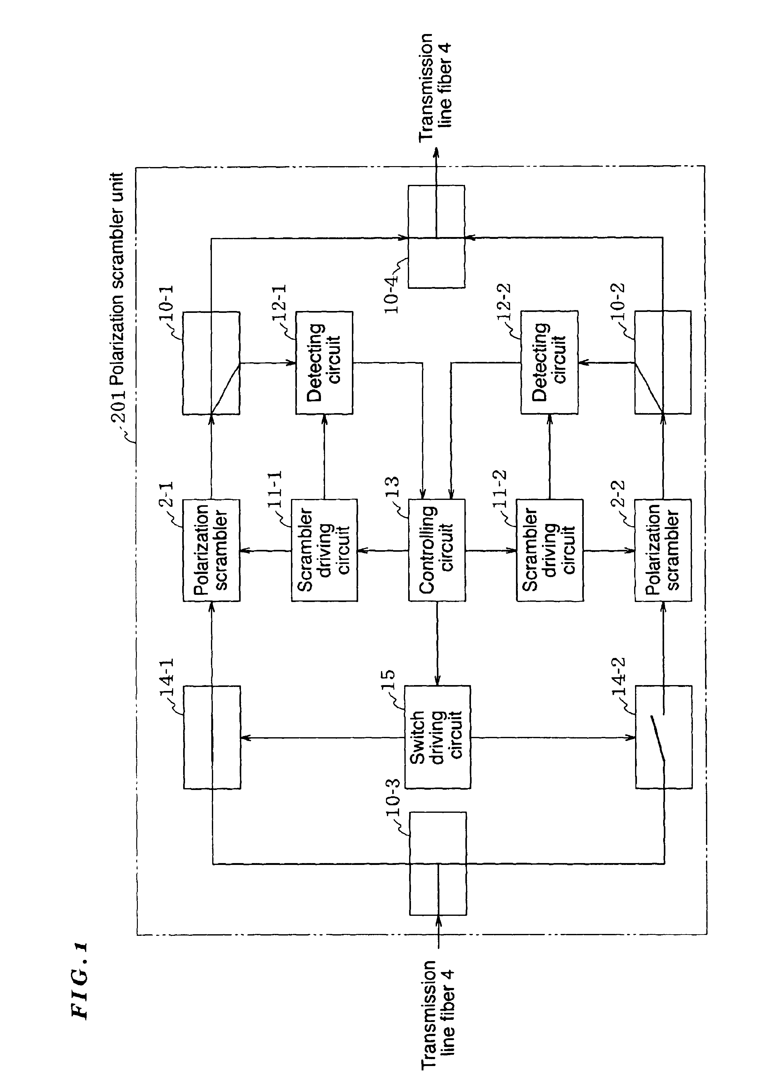
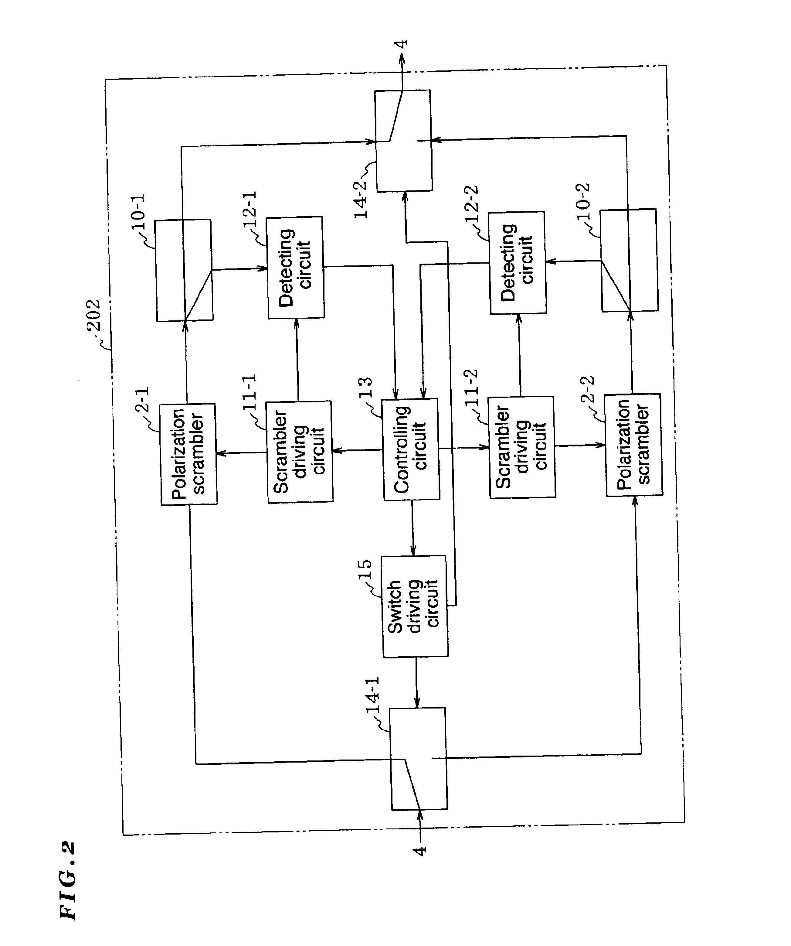
A polarization scrambler unit 201 of the first embodiment is provided with: two polarization scramblers 2-1 and 2-2; a switching unit (described later) for coupling either one of the polarization scramblers 2-1 and 2-2 to a transmission line fiber 4; a detection unit (described later) for detecting an output signal from the polarization scrambler 2-1 (or the polarization scrambler 2-2) coupled to the transmission line fiber 4; and a controlling unit (described later) for switching, by the switching unit, between the polarization scrambler 2-1 and the polarization scrambler 2-2 when a false output signal is detected by the detection unit.
The switching unit is provided with optical switches 14-1 and 14-2 which are inserted between the transmission line fiber 4 and the polarization scramblers 2-1 and 2-2, respectively; a switch driving circuit 15 for opening or closing the optical switches 14-1 and 14-2; an optical coupler 10-3 for branching light from the transmission line fiber 4 to ...
second embodiment
A polarization scrambler unit 204 differs from that of the second embodiment in that an optical coupler 10-5 is inserted between an optical switch 14-1 and a polarization scrambler 2-1, and a clock detecting circuit 16-1 is inserted between a branched output terminal of the optical coupler 10-5 and an input terminal of a scrambler driving circuit 11-1 (an auxiliary system is also configured in the same manner).
The clock detecting circuit 16-1 detects a clock component that is synchronous with the main signal from the signal branched from the optical coupler 10-5, and controls the scrambler driving circuit 11-1 in synchronous with this component (the auxiliary system also works in the same manner). Since the clock component synchronous with the main signal is used, polarization scramble can be performed at high speed.
FIG. 5 is a block diagram showing a fifth embodiment of a polarization scrambler unit according to the present invention. Hereinafter, the fifth embodiment will be descr...
third embodiment
A polarization scrambler unit 205 differs from that of the third embodiment in that a polarization scrambler 2-3 is inserted between an optical coupler 10-5 and a polarization scrambler 2-1 and connected to a scrambler driving circuit 11-3, which in turn is connected to a clock detecting circuit 16-1 (an auxiliary system is also configured in the same manner). The polarization scrambler unit 205 allows both high-speed polarization scramble by the polarization scrambler 2-3 and low-speed polarization scramble by the polarization scrambler 2-1 at the same time (the auxiliary system also works in the same manner).
FIG. 6 is a block diagram showing a sixth embodiment of a polarization scrambler unit according to the present invention. Hereinafter, the sixth embodiment will be described with reference to this drawing. The same or similar components as those shown in FIG. 4 will be denoted by the same reference numerals and thus the descriptions thereof are omitted.
PUM
 Abstract
Description
Claims
Application Information
 - R&D
- Intellectual Property
- Life Sciences
- Materials
- Tech Scout
- Unparalleled Data Quality
- Higher Quality Content
- 60% Fewer Hallucinations
Browse by: Latest US Patents, China's latest patents, Technical Efficacy Thesaurus, Application Domain, Technology Topic, Popular Technical Reports.
© 2025 PatSnap. All rights reserved.Legal|Privacy policy|Modern Slavery Act Transparency Statement|Sitemap|About US| Contact US: help@patsnap.com


