

Hybrid Transmission System
a transmission system and hybrid technology, applied in the direction of transmission elements, electric energy vehicles, toothed gearings, etc., can solve the problems of inefficiency of torque converters, increased system weight and space, and patents that do not teach the use of transmission for hybrid electric vehicles
- Summary
- Abstract
- Description
- Claims
- Application Information
AI Technical Summary
Benefits of technology
Problems solved by technology
Method used
Image

Examples
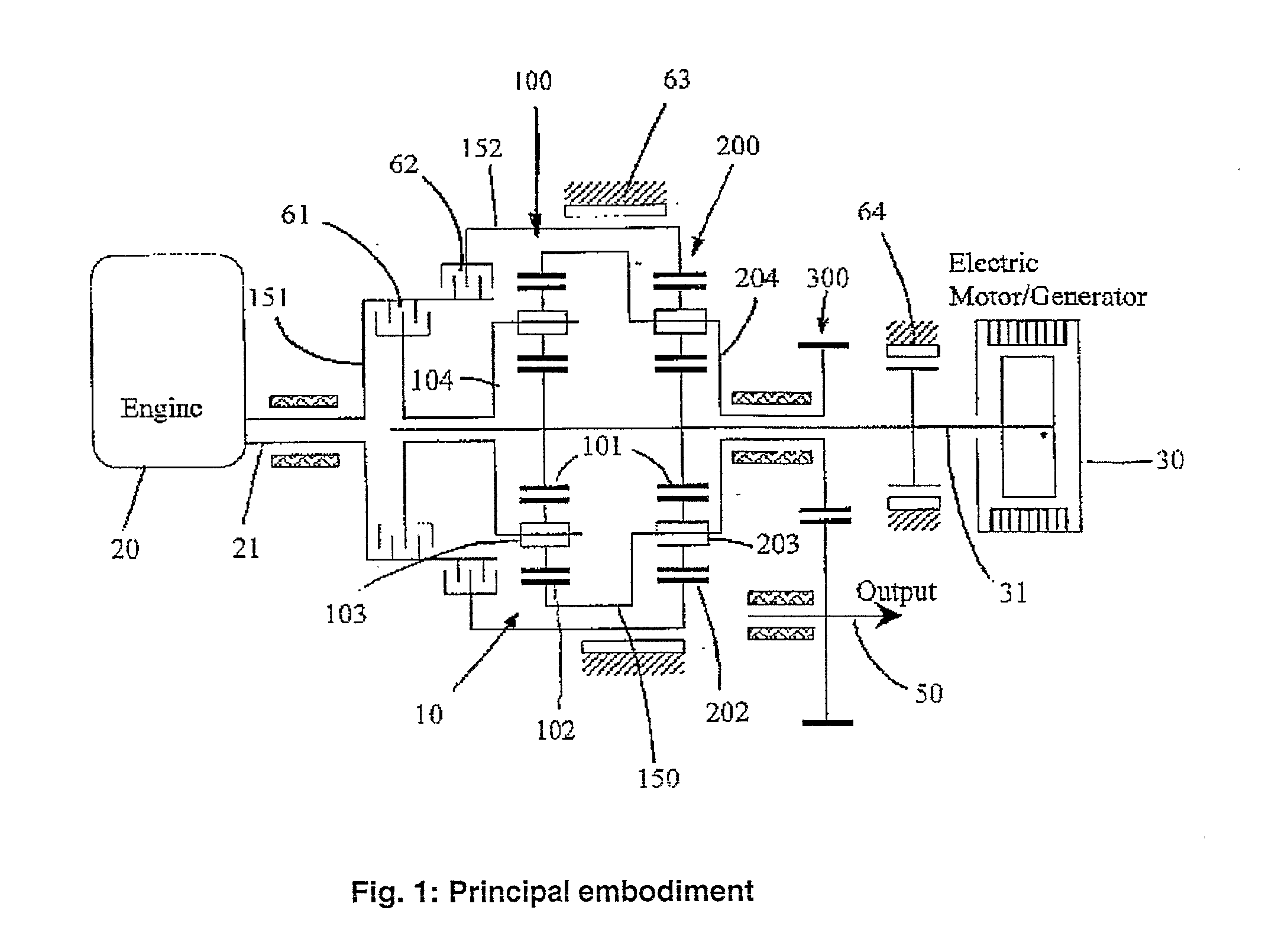
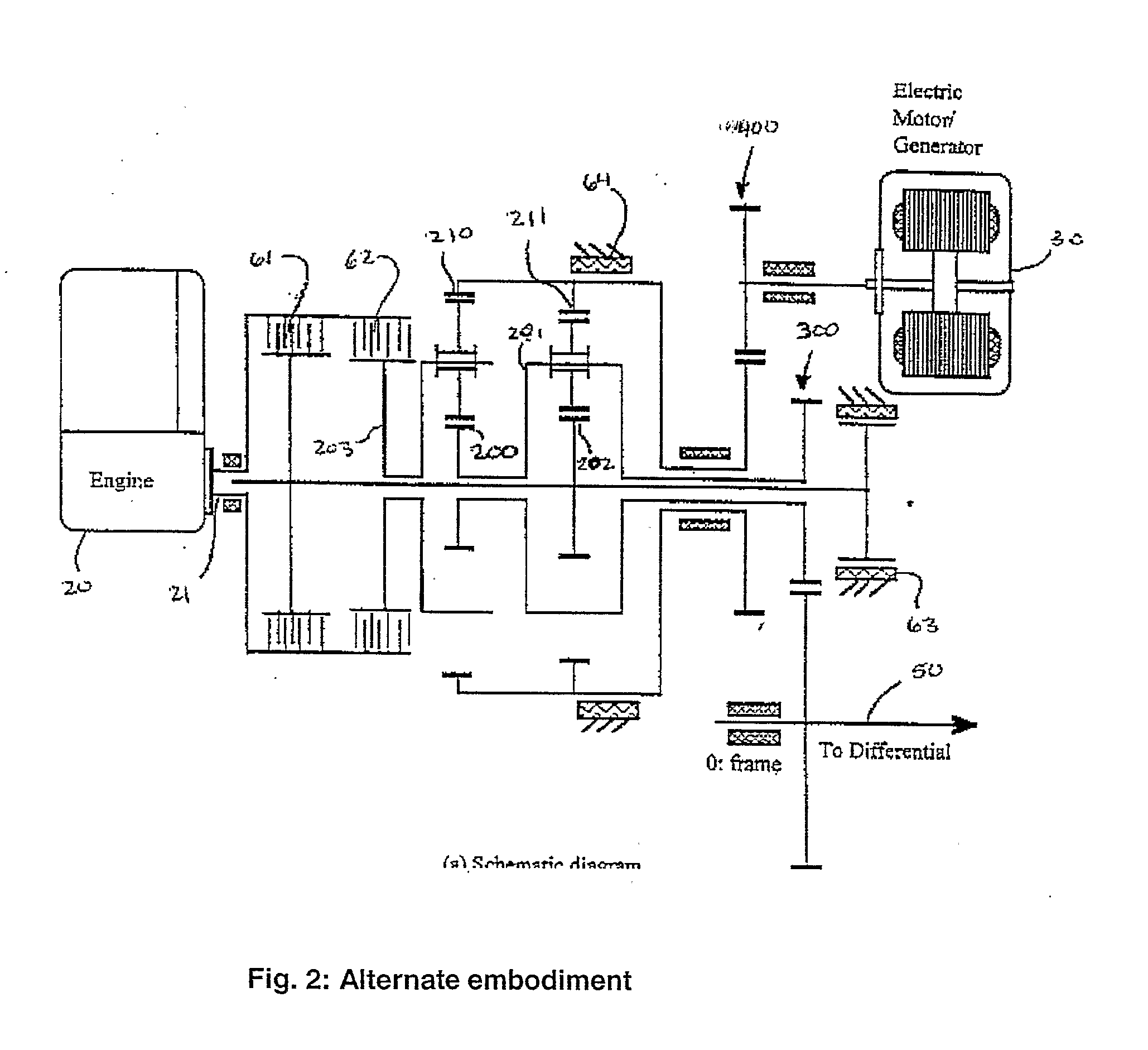
case b
[0056] If only the engine operates and the link driven by the motor is fixed. The equations yield the magnitude of recirculating power to be: 11+Z22-15+Z22-15Z4-21-1
re-circulating in the direction as shown in FIG. 8. This also would always be less than one. Power Mode 2: operation of both the power sources simultaneously leads to even smaller power recirculation, since direction of both the above (Case a and Case b) powers are opposite to each other and both are less than one.
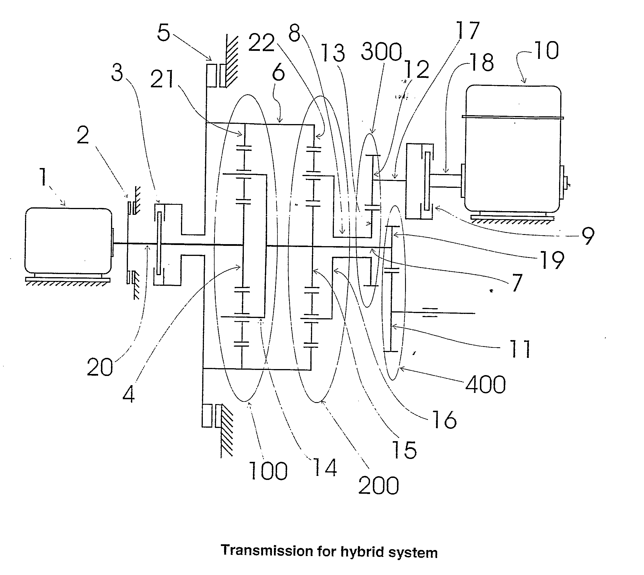
[0057] An improved hybrid transmission has been disclosed that allows the addition of plurality of prime-movers to drive a load using a compound planetary gear train and four torque-transfer devices. The transmission system also allows splitting the power from one of the prime-movers between the charging requirements of the energy storage system and the requirements of the output, in a manner to limit the re-circulating power to a fraction of input power. The transmission system also allows charging the en...
PUM
 Abstract
Description
Claims
Application Information